Phase synchronization device and phase synchronization method
a phase synchronization and phase synchronization technology, applied in phase-modulated carrier systems, digital transmission, pulse automatic control, etc., can solve the problems of high bit error rate, difficulty in simultaneously sending the clock required for demodulation and data, etc., and achieve low cost and power saving
- Summary
- Abstract
- Description
- Claims
- Application Information
AI Technical Summary
Benefits of technology
Problems solved by technology
Method used
Image

Examples
first exemplary embodiment
Explanation of Operation
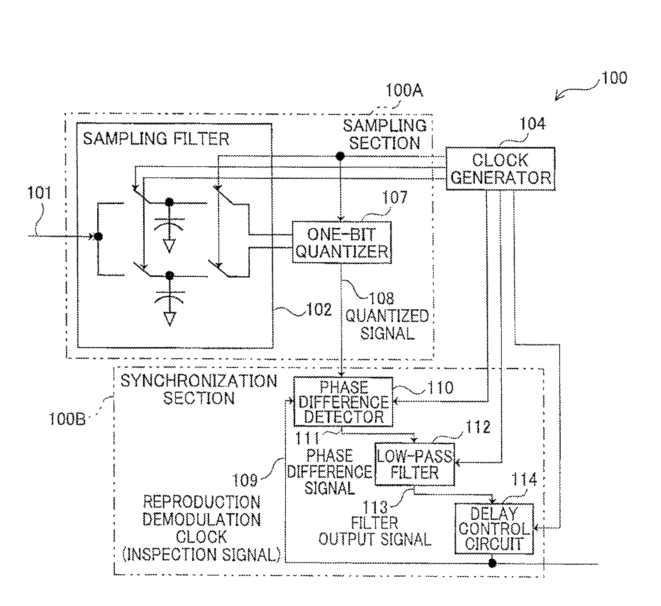
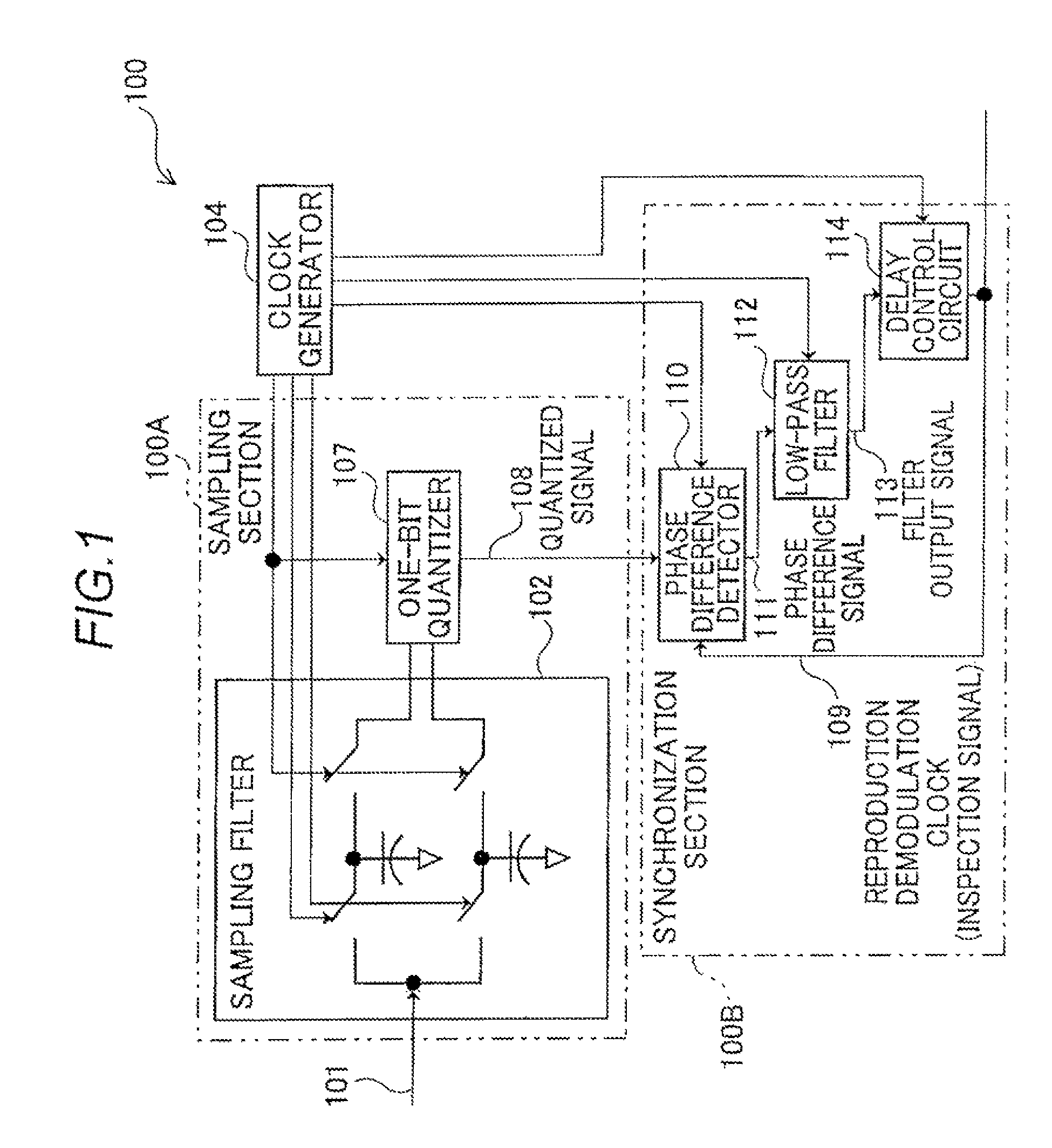
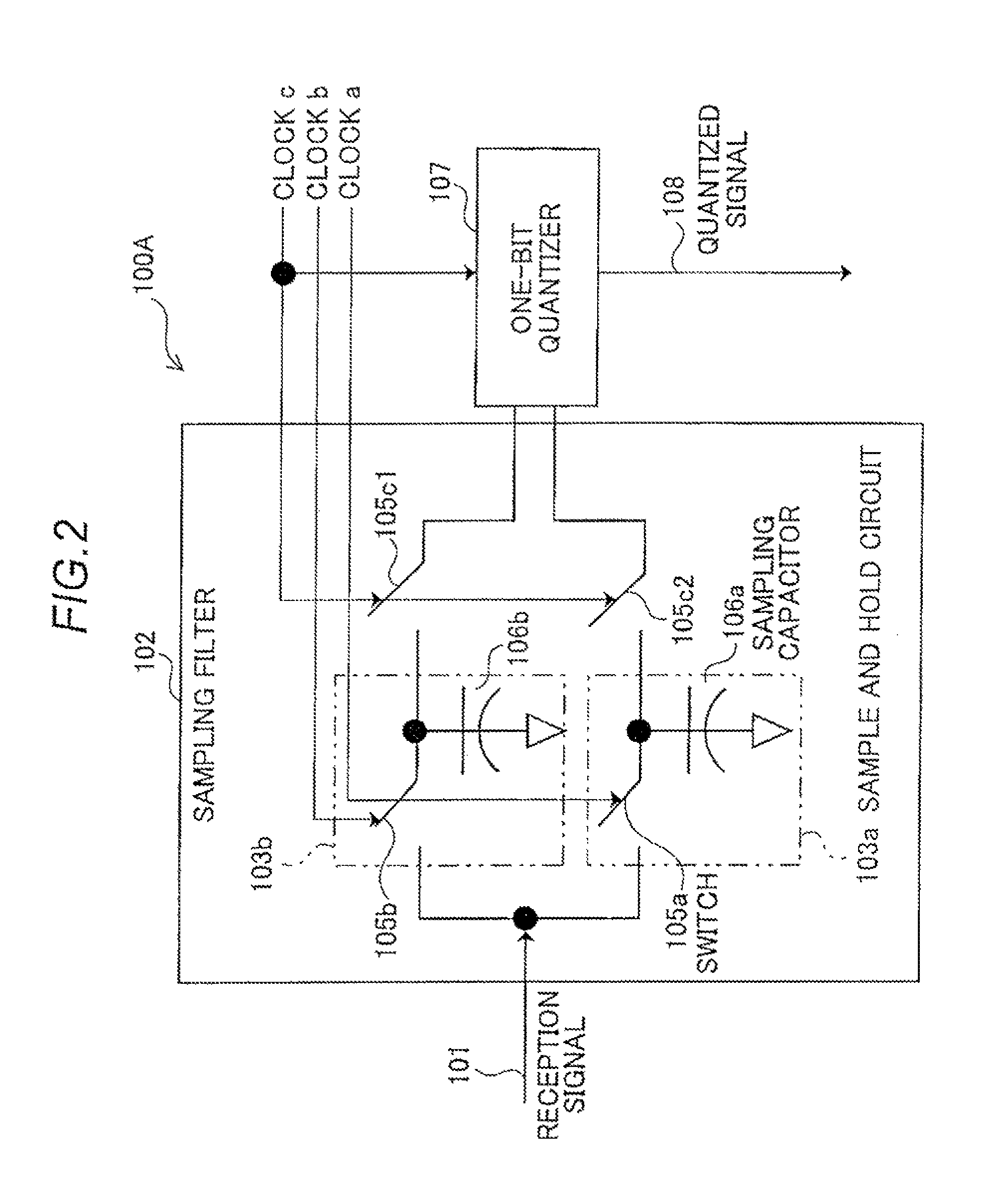
[0049]Operation of the phase synchronization device 100 having the configuration described above will be described with reference to a flowchart illustrated in FIG. 3. The reception signal 101 of a frequency 11 input to the sampling filter 102 is sampled by the sample and hold circuits 103a and 103b according to the clocks “a” and “b” each having a frequency fs0 and the sampled values are held by the sample and hold circuits 103a and 103b. As a result, the reception signal 101 is converted from a continuous-time signal into a discrete-time signal (step S1).
[0050]FIG. 4 illustrates an example of the sampling performed by the sampling filter 102. As illustrated in FIG. 4, the reception signal 101 is converted into discrete signals of A1 to A4 and A9 to A12 according to the clock “a” and discrete signals of B5 to B8 and B13 to B16 according to the clock “b”. The values of A1 to A4 are held in the sampling capacitor 106a as an analog addition value (A1+A2+A3+A4),...
second exemplary embodiment
Explanation of Operation
[0080]Operation of the phase synchronization device 200 having the configuration described above will be described. The operation of the synchronization section 100B according to the present exemplary embodiment is the same as that of the first exemplary embodiment, and the description thereof will be omitted. In the following, a part of the operation of the sampling section 200A different from that of the sampling section 100A of the first exemplary embodiment will mainly be described.
[0081]The multi-phase generator 215 divides the phase of the clock “a” input from the clock generator 104 to generate clocks a1 to a4 of four phases and outputs the generated clocks to the phase compensator 216. The phase compensator 216 adjusts the correlation skews of the clocks a1 to a4 and sequentially inputs the resultant clocks to the sample and hold circuit 203a. More concretely, as illustrated in FIG. 10, the clock a1 is input to the switch 105a1 of the sample and hold ...
PUM
 Abstract
Description
Claims
Application Information
 - R&D
- Intellectual Property
- Life Sciences
- Materials
- Tech Scout
- Unparalleled Data Quality
- Higher Quality Content
- 60% Fewer Hallucinations
Browse by: Latest US Patents, China's latest patents, Technical Efficacy Thesaurus, Application Domain, Technology Topic, Popular Technical Reports.
© 2025 PatSnap. All rights reserved.Legal|Privacy policy|Modern Slavery Act Transparency Statement|Sitemap|About US| Contact US: help@patsnap.com