Electrical connector assembly having pick-up cap

a technology of electric connectors and pickup caps, which is applied in the direction of electrical equipment, live contact access prevention, coupling device connections, etc., can solve the problems of latches b and difficult latch removal

Inactive Publication Date: 2012-03-27
HON HAI PRECISION IND CO LTD
View PDF5 Cites 20 Cited by
  • Summary
  • Abstract
  • Description
  • Claims
  • Application Information

AI Technical Summary

Benefits of technology

[0007]Accordingly, an object of the present invention is to provide an electrical connector assembly having a pick-up cap which can protect a latch thereof from breaking, resulted from excessive deflection.

Problems solved by technology

In above process, the second end will easily trap into a gap between the insulative housing 3′ and the stiffener, that may resulting difficult removal of the latches 22′ therefrom and in worse scenario, the latches 22′ will be broken.

Method used


Image

  • Electrical connector assembly having pick-up cap
  • Electrical connector assembly having pick-up cap
  • Electrical connector assembly having pick-up cap

Examples


Embodiment Construction

[0019]Reference will now be made to the drawings to describe the present invention in detail.

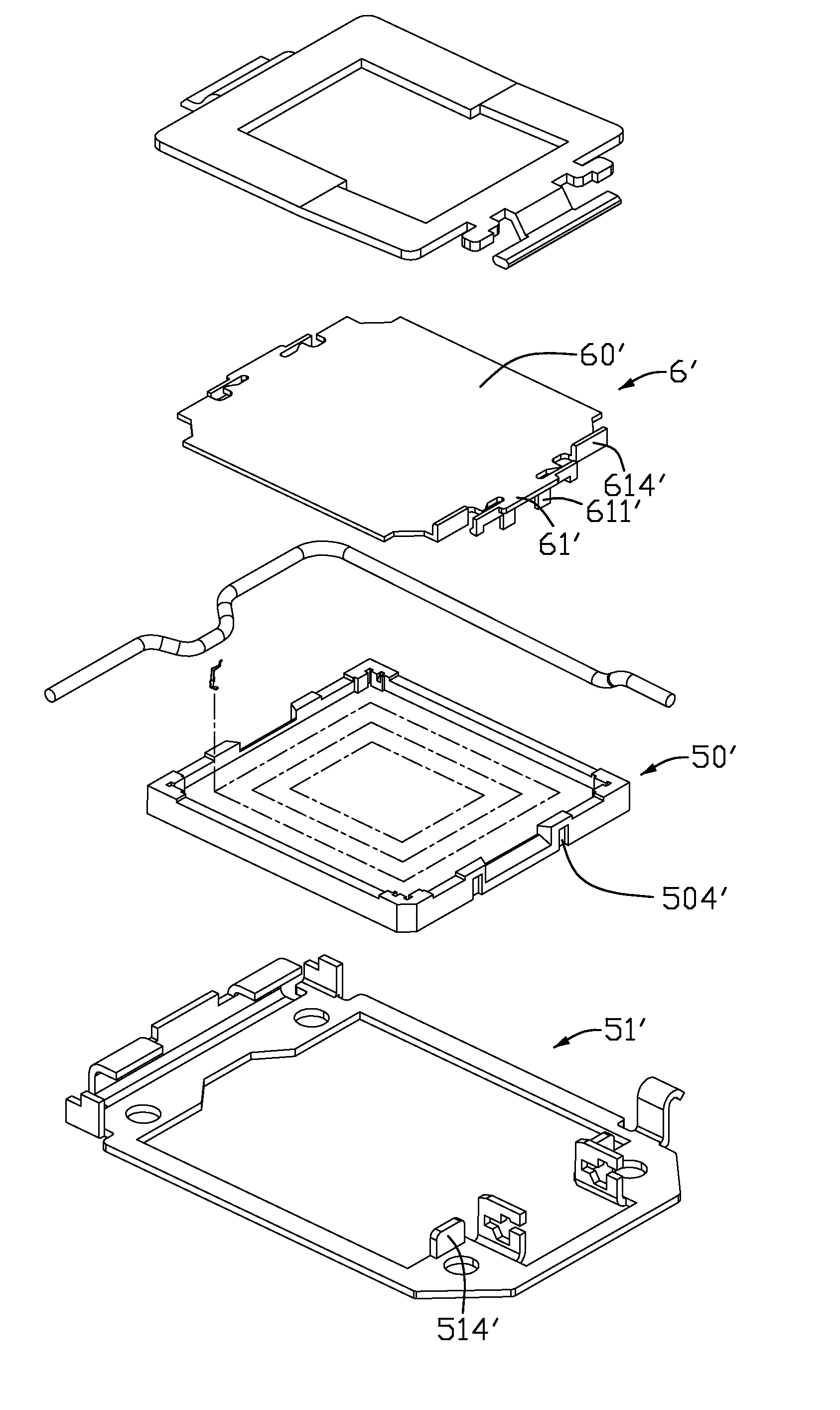
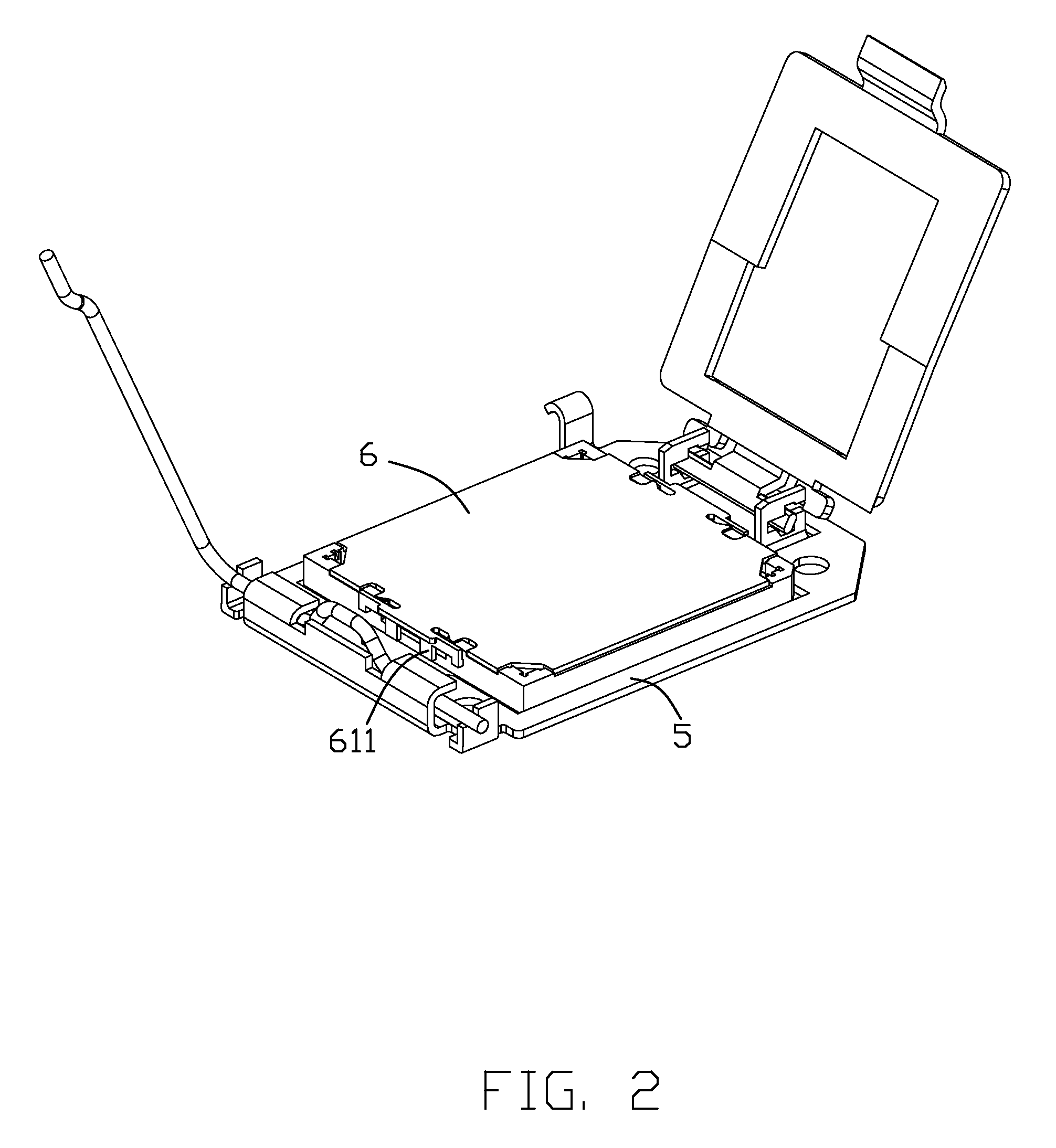
[0020]FIG. 2 shows an electrical connector assembly for electrically connecting an electronic package (not shown) to a printed circuit board (not shown). The electrical connector assembly comprises an electrical connector 5 and a pick-up cap 6 assembled to the electrical connector 5.

[0021]FIG. 2 and FIG. 3 show a first embodiment of the present invention. The electrical connector 5 includes an insulative housing 50 with a plurality of contacts 7, a frame 51 surrounding the insulative housing 50, a load plate 52 mounted to one end of the frame 51, and a lever 53 mounted to an opposite end of the frame 51.

[0022]The insulative housing 50 is formed with a rectangular configuration and molded from resin or the like. The insulative housing 50 has a plurality of periphery walls 501 extending upwardly from an upper surface of the insulative housing 50. The upper surface and the periphery walls 501 d...


PUM


Abstract

A pick-up cap includes a main portion having a planar top surface with a first end and a second end opposite to the first end. Four latches are positioned at the two ends of the main portion and extend from the main portion, respectively. Each latch has a hook extending downwardly. And a supporting portion extending downwardly and being adjacent to the hook. The supporting portion is lower than the hook in a vertical direction to engage with an insulative housing to protect the hook during the pick-up cap is disassembled from the insulative housing.

Description

BACKGROUND OF THE INVENTION[0001]1. Field of the Invention[0002]The present invention relates to an electrical connector assembly, and more particularly to an electrical connector assembly with a pick-up cap, which can protect a latch thereof from breaking resulted from excessive deflection.[0003]2. Description of the Prior Art[0004]U.S. Pat. No. 7,001,197 issued to Shirai on Feb. 21, 2006 discloses a typical electrical connector comprising an insulative housing having a plurality of contacts. The insulative housing has a top surface for receiving an electronic package. A cover is pivotally mounted on a first end of the insulative housing and pivotally rotates between an opened position and a closed position. The cover has an opening in a center area so that an electronic package passes through the opening to electrically connect to the contacts. A lever is pivotally mounted to a second end of the insulative housing. The lever has a locking portion for locking the cover in the close...

Claims


Application Information

Patent Timeline
Patent Type & Authority Patents(United States)
IPC IPC(8): H01R13/60
CPCH05K7/1007Y10S439/94
Inventor FAN, CHIA-WEI
Owner HON HAI PRECISION IND CO LTD
Why Eureka
Try Eureka