
Furniture and method of furniture component attachment

a technology of furniture and components, applied in the field of furniture and furniture components, can solve the problems of limiting assembly options, affecting the aesthetic effect of chairs or articles, and requiring significant expense in the purchase of one or more molds for such overmolding

Active Publication Date: 2012-04-17
KNOLL INC
View PDF45 Cites 39 Cited by
  • Summary
  • Abstract
  • Description
  • Claims
  • Application Information

AI Technical Summary

Benefits of technology

The patent describes methods for attaching furniture components together using polymeric materials and infrared light energy. The methods involve positioning a back skin adjacent to a back frame, folding the back skin over the back frame, positioning a cross member between the folded over back skin and the back frame, and heating the cross member to bond the components together. The patent also describes the use of stakes and projections for attachment, as well as the use of a base and tilt mechanism for the chair. The technical effects of the patent include improved attachment methods for furniture components, increased efficiency in the heating process, and improved flexibility in the chair design.

Problems solved by technology

Such visible elements may detract from the aesthetic effect provided by a chair or article of furniture
The use of such overmolding often requires significant expense in the purchasing of one or more molds.
Further, overmolding may only be utilized for certain components that meet particular structural requirements or that are only accessible at a select few steps in a chair manufacturing process, which may limit assembly options and increase the costs of manufacturing an article of furniture, such as a chair.

Method used


Image

  • Furniture and method of furniture component attachment
  • Furniture and method of furniture component attachment
  • Furniture and method of furniture component attachment

Examples


Embodiment Construction

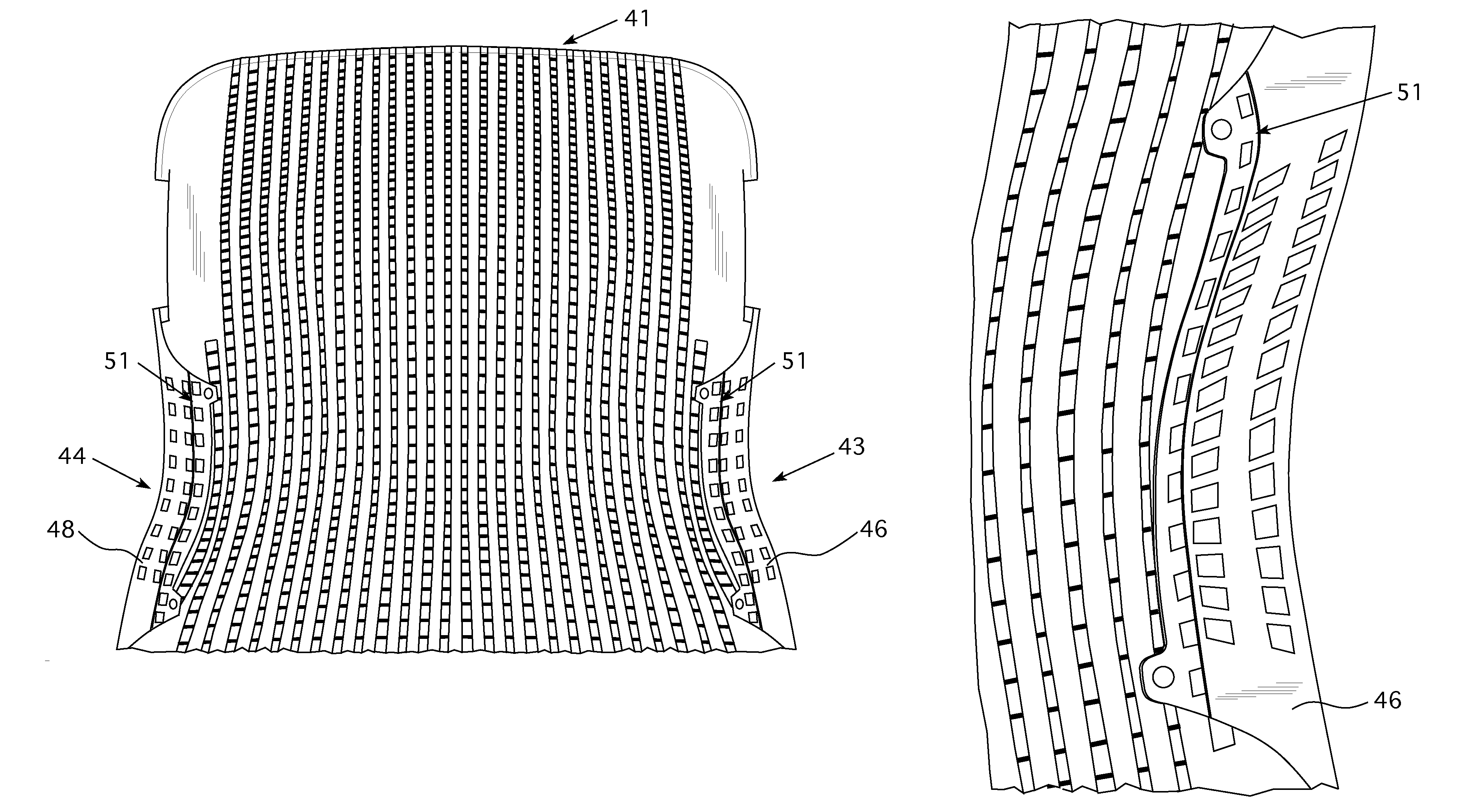
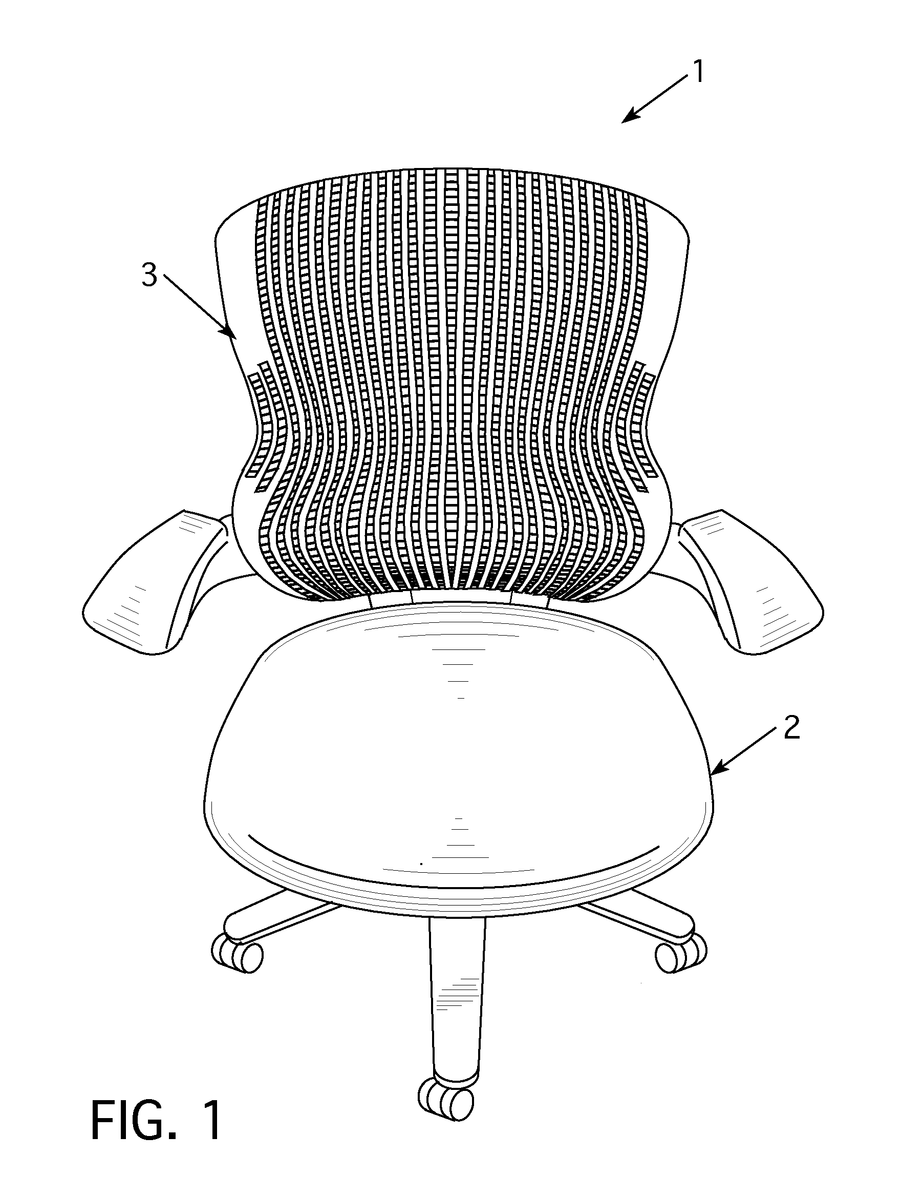
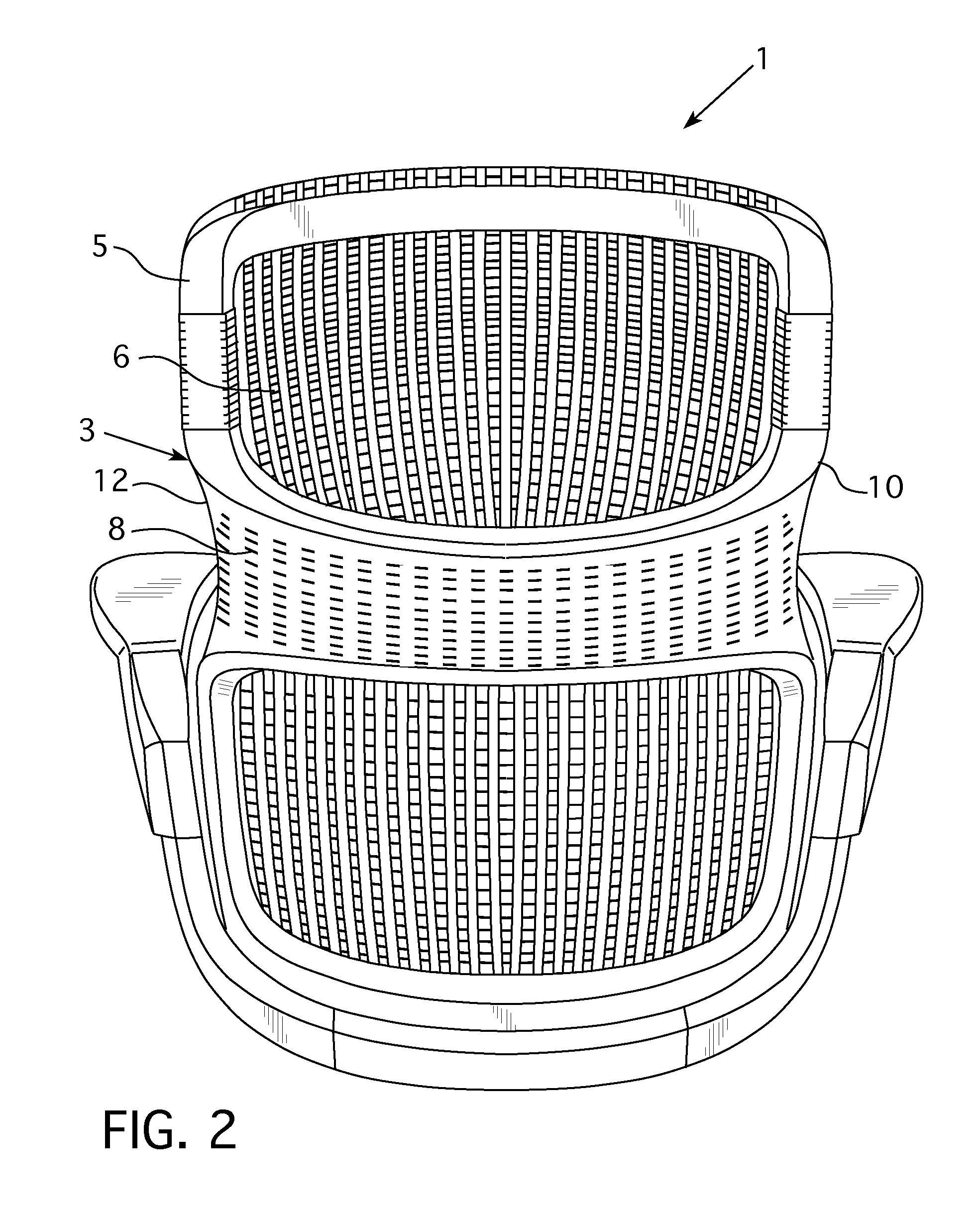
[0031]Referring to FIGS. 1-2 a first present preferred embodiment of a chair 1 has a seat 2 and a back 3. The back 3 of the chair 1 includes a back frame 5. The back frame 5 is attached to the base of the chair and is moveable relative to the seat 2 such that the back 3 can recline. For instance, the back frame 5 may be attached to a control mechanism to provide such recline movement. Preferably, the seat 2 is attached to the base of the chair such that the seat 2 is raised when the back 3 is reclined. The chair 1 may have armrests that are adjustably attached to the base of the chair or the back frame 5 of the chair.

[0032]The back frame 5 preferably has a “FIG. 8” configuration defined by an upper first hoop attached to a lower second hoop by a central post. The back frame 5 is preferably composed of plastic or an elastomeric material. A back skin 6 is attached to the back frame 5. The back skin is preferably an elastomeric sheet of material with holes formed therein. Preferably, t...


PUM

PropertyMeasurementUnit
infrared energyaaaaaaaaaa
polymericaaaaaaaaaa
elastomericaaaaaaaaaa

Abstract

A method of attaching furniture components includes providing a first furniture component that may be comprised of polymeric material, positioning a second furniture component adjacent to the first furniture component, positioning stakes attached to the second component through holes formed in the first component, and heating the stakes to bond portions of the second component to portions of the first component. The second component may also be comprised of polymeric material and the stakes may be integral with the second component or formed on the second component. Chairs or other furniture such as office furniture may include components attached together by embodiments of the disclosed method. In some embodiments of the method, a second component may also have projections that are positioned through holes in a third furniture component that may subsequently be heated to bond the third component to the second component.

Description

CROSS REFERENCE TO RELATED APPLICATION[0001]The present application claims priority to U.S. Provisional Patent Application Ser. No. 61 / 155,298, filed on Feb. 25, 2009. The entirety of U.S. Provisional Patent Application Ser. No. 61 / 155,298 is incorporated herein by reference.FIELD OF THE INVENTION[0002]The invention relates to articles of furniture, such as chairs and methods of attaching furniture components.BACKGROUND OF THE INVENTION[0003]Chair components are often attached together by fastening mechanisms. Some fastening mechanisms, such as screws or bolts, often include portions that are visible to a seated user or a potential customer. For example, the head of a screw or bolt may be positioned along an outer portion of a frame member of a chair that can be seen by a user or potential customer. Such visible elements may detract from the aesthetic effect provided by a chair or article of furniture[0004]Some chair components may be attached together by overmolding one component o...

Claims


Application Information

Patent Timeline
Patent Type & Authority Patents(United States)
IPC IPC(8): A47C7/02A47C7/22
CPCA47C31/02Y10T29/49826
Inventor MASOUD, KHALIDDESKEVICH, ADAM
Owner KNOLL INC
Learn More