Rest module with a first partial module with direct access to a possible second partial module

a technology of partial modules and rest modules, applied in the field of rest modules, can solve the problems of not being optimally designed in the sense of room and space configuration, not offering the full technical height over the whole area, and the so-called first class area is commonly very commodious and spatially wide, so as to achieve the effect of improving the rest of the crew

Inactive Publication Date: 2012-04-24
AIRBUS OPERATIONS (SAS)
View PDF16 Cites 32 Cited by
  • Summary
  • Abstract
  • Description
  • Claims
  • Application Information

AI Technical Summary

Benefits of technology

[0016]According to this exemplary embodiment of the invention the space between this first and second avionics bay is used in a space saving way. Furthermore the housing of the rest modules comprising or being the outer walls of the rest module may be constructed in such a way, that is may be used as protection element between the first and second avionics bays. In case of e.g. a fire or an explosion in the required distance area between the two avionics bay, the presence of the rest module may securely protect the electronical components. Therefore the rest module may comprise e.g. fireproof walls, bullet proof walls or explosion resistant walls or any combination of these.
[0052]As the first partial module is located in the electronic bay which is located close to nose of the aircraft the rest module is close to the cockpit. Due to higher security standards for the flight crew a special flight crew security region may be compulsory within the aircraft. The installation of the first partial module into the area between the cargo wall and the region of the nose landing gear allows technically to insert the first partial module in such a special flight crew security region. It might thus be possible to build a complete mechanical unit by the shown first partial module and the above located cockpit with maybe further elements like e.g. lavatories. Thus a short and safe way for the flight crew into the first partial module in the electronic bay can be realized. Thereby a flight crew member does not need to leave this spatially divided and secure flight crew area on his way to the electronic bay.

Problems solved by technology

On the one hand the habitation area in the inner side of these compartments is commonly very narrow and on the other hand the following passenger area for example the so-called first class area is commonly very commodious and spatially wide.
Such a first class area may eventually not offer the full technical height over the whole area.
Further on known solutions of crew rest compartments or flight crew rest compartments do not provide a spatial division or separation between different cabins for single crew members and are therefore not optimally designed in the sense of room and space configuration.
The privacy may therefore not be provided during a rest session of an user.
Because the crew is joined by a second pilot in only 70 to 80% of the flights, the second bed and all its appropriate components may be transported unnecessarily.
The second bed may require a lot of storage or loading space which volume may be urgently needed in airplanes.

Method used


Image

  • Rest module with a first partial module with direct access to a possible second partial module
  • Rest module with a first partial module with direct access to a possible second partial module
  • Rest module with a first partial module with direct access to a possible second partial module

Examples


Embodiment Construction

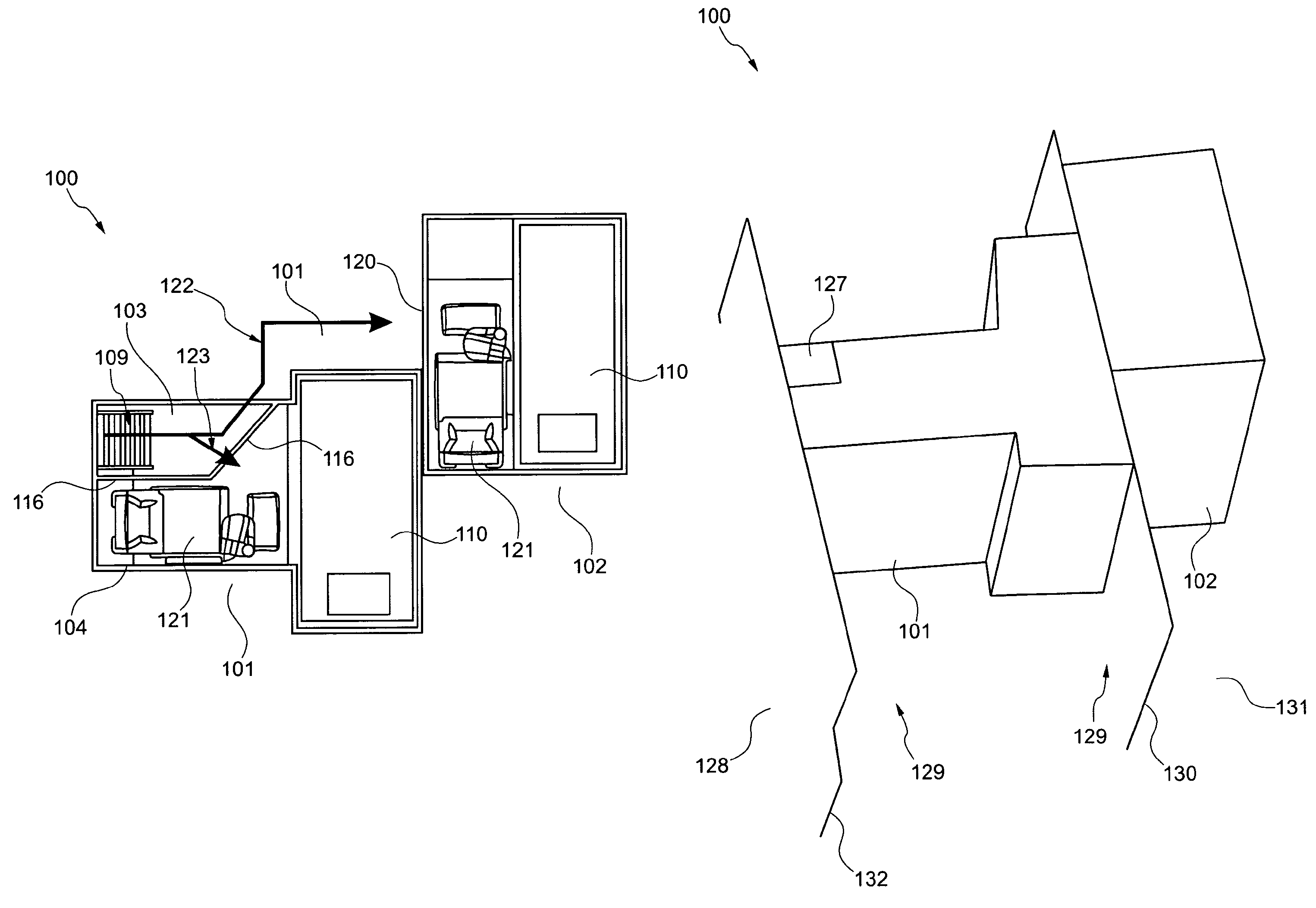
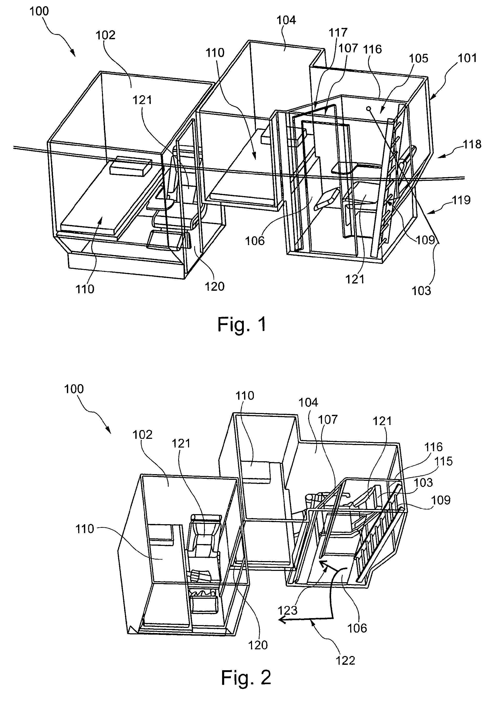
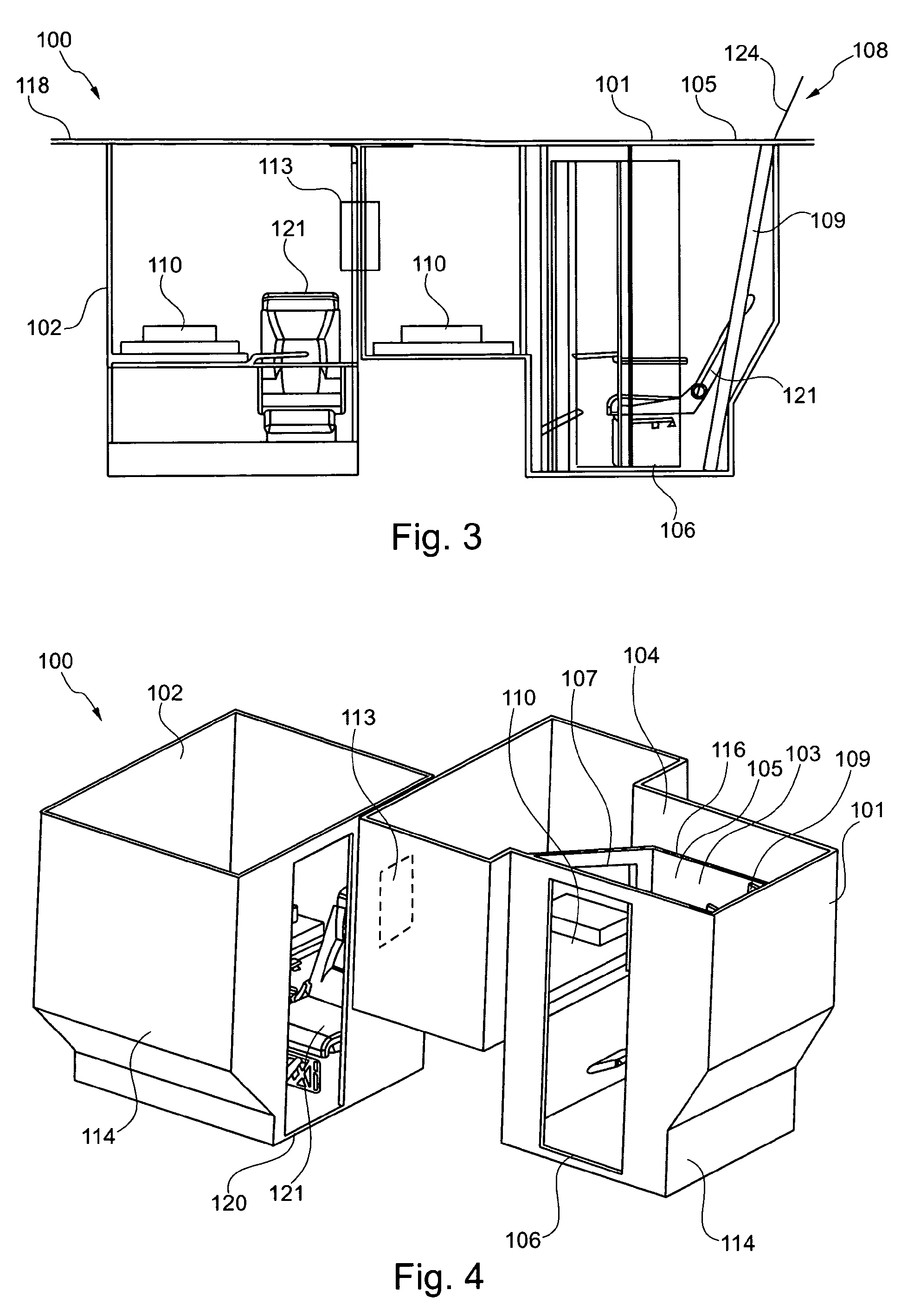
[0070]Similar or relating components in the several figures are provided with the same reference numerals. The view in the figure is schematic and not fully scaled.

[0071]FIGS. 1, 2 and 4 illustrate schematic views of exemplary embodiments of the present invention. A shown rest module 100 comprises a first partial module 101 and a second partial module 102, while the first partial module is spatially divided by a wall 116. This wall creates a first section 103 and a second section 104. The wall 116 further on offers a door 117 that guarantees an access from the first section of the first partial module into the second section. All together the first section comprises three openings, the first opening 105, the second opening 106 and the third opening 107. The first opening 105 is an opening that leads to an above-located area of the aircraft 108. This area is only indicated by the floor of the above-located area 118. The first opening 105 therefore is an opening in the floor of the ab...


PUM


Abstract

The invention relates to a rest module for accommodating a least one crew member of an aircraft, wherein the module comprises a first partial module. Further on the first partial module comprises a first section and a second section; wherein the first section and the second section are spatially divided. The first section comprises a first opening, a second opening and a third opening, wherein the three openings are different from each other. The first opening is adapted for providing an access from an above located area of the aircraft, the second opening is adapted for providing an access from the first section to a second partial module and the third opening is adapted for providing a separate access from the first section to the second section.

Description

CROSS-REFERENCE TO RELATED APPLICATIONS[0001]This application is a national phase entry under 35 U.S.C. §371 of International Application No. PCT / EP2008 / 065543, filed Nov. 14, 2008, published in English, which claims the benefit of the filing date of European Patent Application No. EP 07 022 520.6 filed Nov. 20, 2007 and of the U.S. Provisional Patent Application No. 61 / 003,744, filed Nov. 20, 2007, the disclosures of which applications are hereby incorporated herein by reference.TECHNICAL FIELD[0002]The present invention relates to a rest module, the use of a rest module in an aircraft and an aircraft comprising a rest module.BACKGROUND OF THE INVENTION[0003]Today's commercial aircraft cabins are designed to accommodate crew members in special rooms. More precisely such rooms may be designed as so-called crew rest compartments or rest modules which belong, according to statutory provisions, to the mandatory equipment of airplanes for long distance flights. Therefore, according to i...

Claims


Application Information

Patent Timeline
Patent Type & Authority Patents(United States)
IPC IPC(8): B64D11/00
CPCB64D11/00B64D2011/0046B64D2011/0076Y02T50/46Y02T50/40
Inventor JOANNIS, GILLESVOELKNER, KATHRINCHOURREAU, YANNICKGELDIEN, MARTINGOLUBOVIC, DEJAN
Owner AIRBUS OPERATIONS (SAS)
Why Eureka
Try Eureka