Neck brace

Active Publication Date: 2012-04-24
ALPINESTARS RES SPA
View PDF58 Cites 6 Cited by
  • Summary
  • Abstract
  • Description
  • Claims
  • Application Information

AI Technical Summary

Benefits of technology

[0009]The main object of the present invention is to provide a nec

Problems solved by technology

However, these collars can be uncomfortable and unduly restrictive to head movements in ordinary situations, e.g. when a motorcyclist wishes to look from side to side while driving.
Neck braces of this type have the major drawback that they are difficult

Method used


Image

  • Neck brace
  • Neck brace
  • Neck brace

Examples


Example

[0028]In the following, references with suffix “a” and “b” are to be understood to be mean equal or corresponding parts in the neck-brace, since the same or similar components are designed with the same numerals, which for sake of conciseness will not be described more than once.

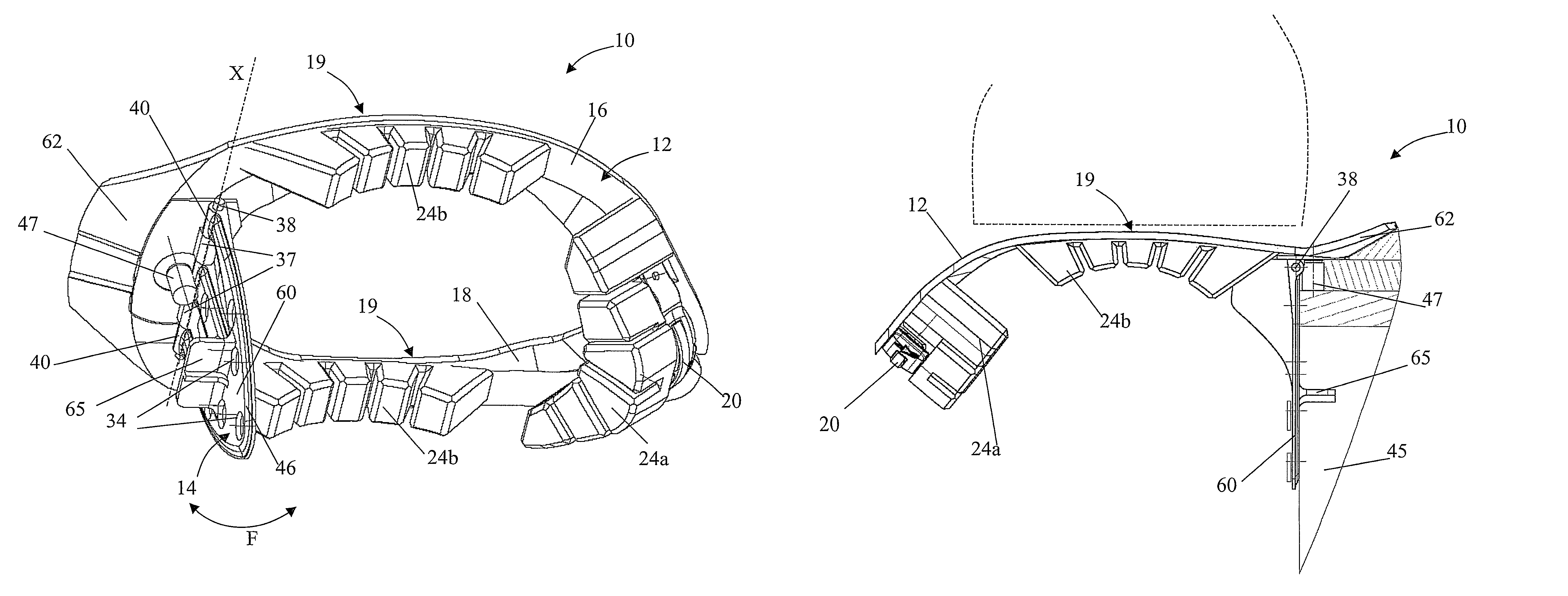
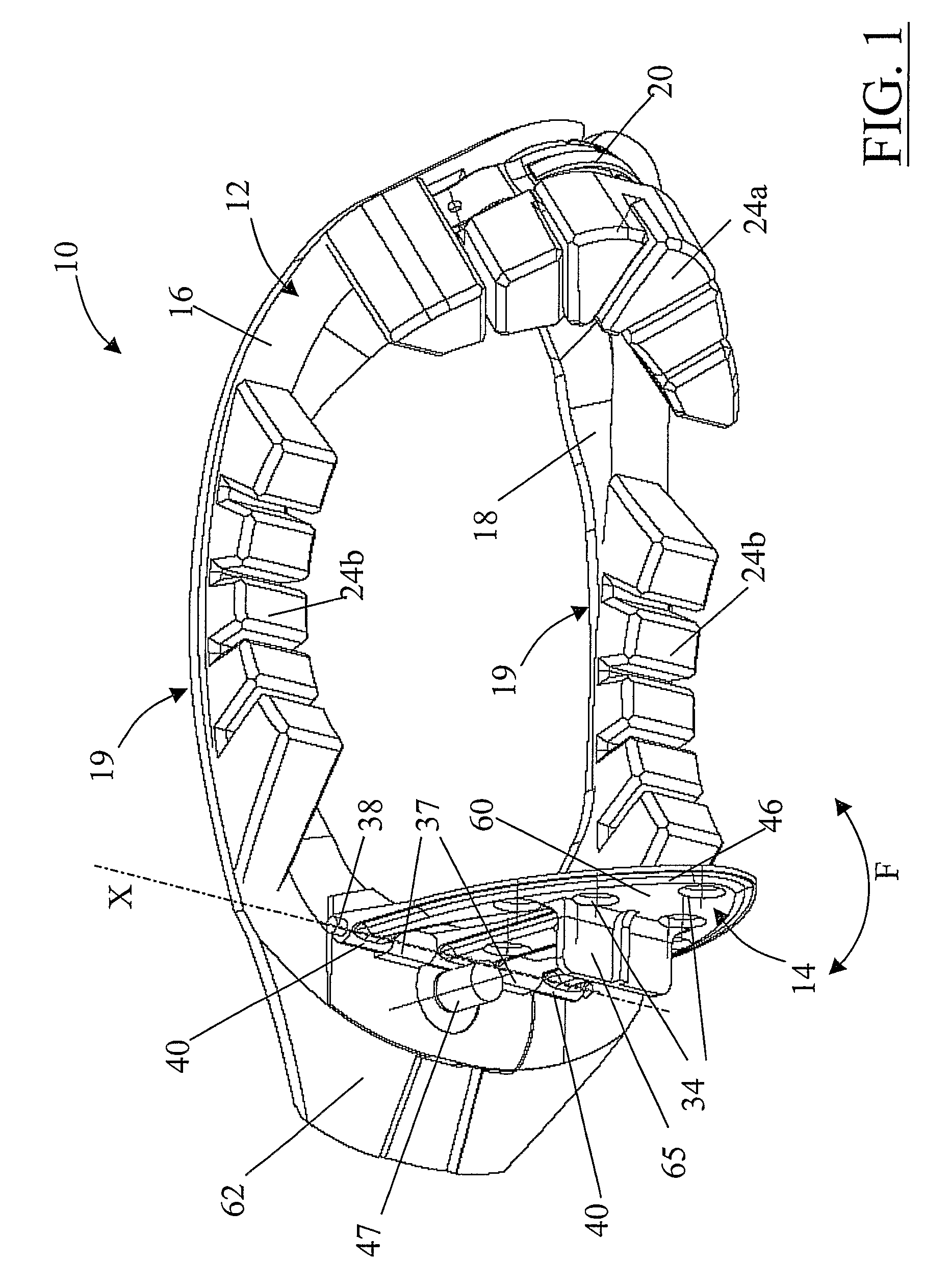
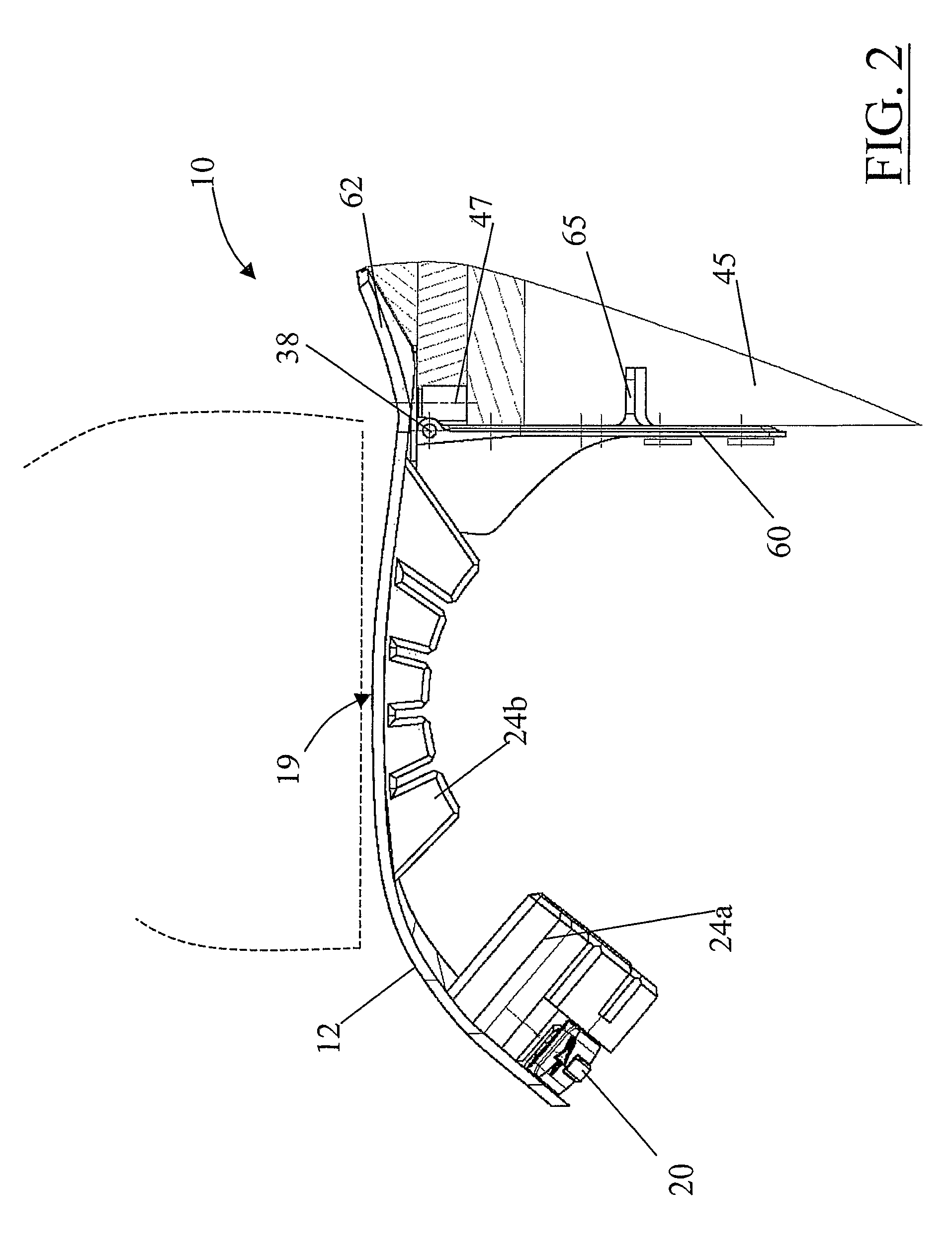
[0029]With reference first to FIG. 1, a neck brace, generally designed with reference 10, has a collar member 12, which, in use, extends around a wearer's neck, and a rear member 14, which, in use, rests upon the wearer's back.

[0030]The collar member 12 comprises two semi-circular halves 16, 18 which are frontally (i.e. at the wearer's chin) connected through closure means, in the example a releasable buckle 20, and, in the back (i.e. at a wearer's nape), jointed by pivoting means, in the example a hinge 22.

[0031]By releasing the buckle 20, the two halves 16, 18, due to the hinge 22, can rotate outward, thereby opening the collar member 12 and making it possible for a wearer to insert the neck.

[0032]The two ...


PUM


Abstract

A neck brace (10; 110; 210) having a collar member (12; 212) to be arranged around a wearer's neck, and a rear member (14; 214) extending from, the collar member and to be abutted on the wearer's back. The brace further comprises pivoting means (37, 38, 40, 276a, 278, 280a, 280b, 280c) for pivoting the collar member and the rear member relative to each other about a pivoting axis (X; Y) which, when in use, is substantially parallel to the wearer's shoulders.

Description

CROSS-REFERENCE TO RELATED APPLICATIONS[0001]This application is a US 371 national stage entry of International Application No. PCT / IT2007 / 000153, filed Mar. 1, 2007.BACKGROUND[0002](1) Field of the Invention[0003]The present invention relates to a neck brace used to enhance the protection given by a helmet to the head and neck of a wearer, particularly a rider in a sport activity, e.g. motor racing.[0004](2) Description of Related Art[0005]It is nowadays compulsory for participant in such sport activities as motor racing to wear helmets in order to protect their heads in the event of an accident.[0006]In order to assure an additional protection to the wearer the use of collars made of resilient material, typically stiff foam, placed between the wearer's upper body and the base of a helmet, has been proposed (see for instance U.S. Pat. No. 6,058,517). The goal is to limit to some degree the movement of the head in case of an impact by reducing the gap in which the helmet can move. H...

Claims


Application Information

Patent Timeline
IPC IPC(8): A61F5/00A41D13/00
CPCA41D13/0512A63B71/1291A61F5/055A42B3/0473A41D2600/102
Inventor MAZZAROLO, GIOVANNI
Owner ALPINESTARS RES SPA
Why Eureka
Try Eureka