Device and method for operation of a fuel cell

a fuel cell and device technology, applied in the direction of fuel cells, solid electrolyte fuel cells, electrical devices, etc., can solve the problems of high complexity of one of the raw-material gases as a function of the instantaneous feed pressure of the other raw-material gas, and the outlet valve of a gas cylinder or a fuel reservoir of this type cannot be adjusted in practice sufficiently quickly, continuously and accurately for defined pressure changes, etc., to avoid local overloading, reduce volume, and low mass

US8168345B2Active Publication Date: 2012-05-01DIEHL AEROSPACE GMBH
15 Cites 0 Cited by

Patent Information

Authority / Receiving Office
US · United States
Patent Type
Patents(United States)
Current Assignee / Owner
Publication Date
2012-05-01

Smart Images

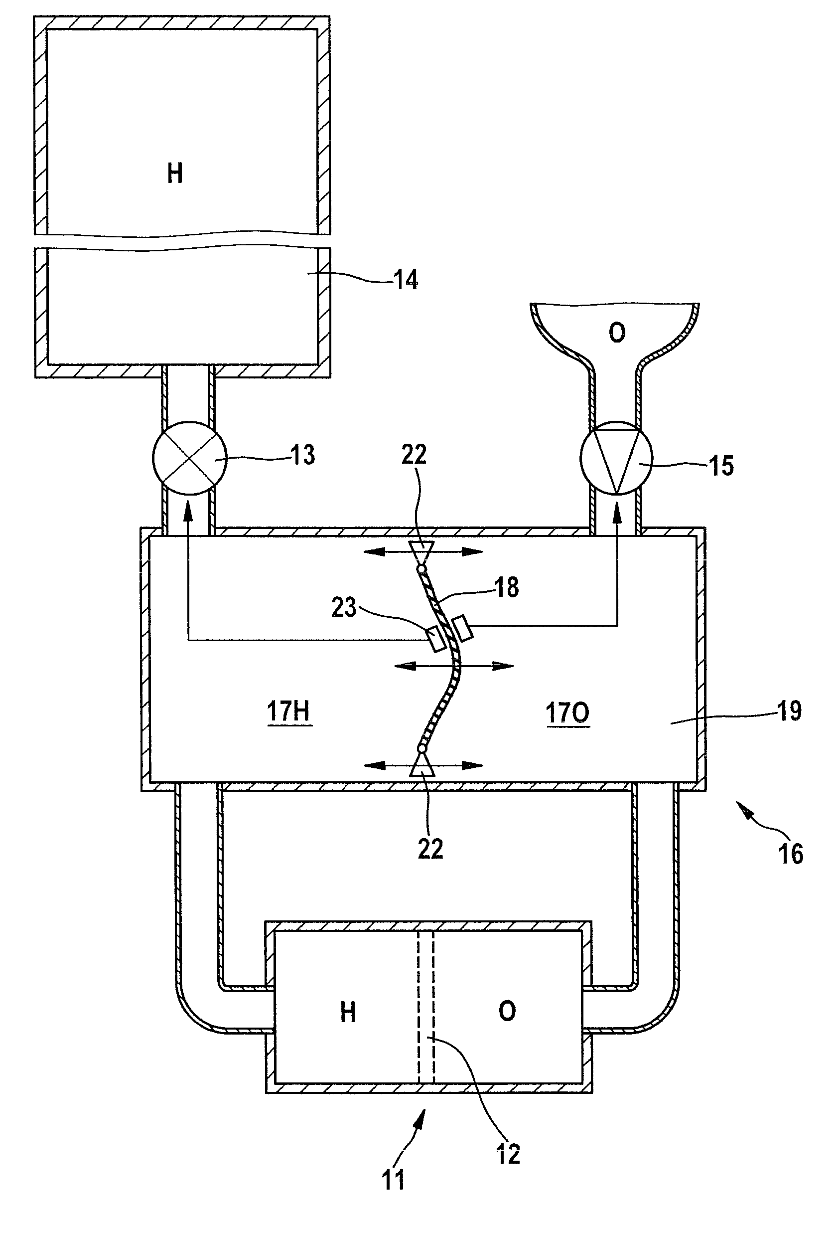
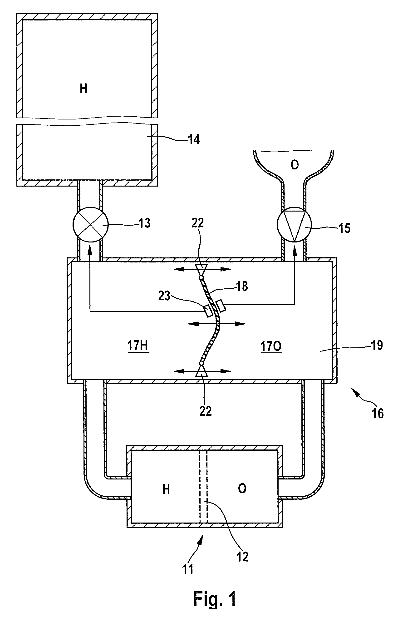
  • Figure 1
    Figure 1
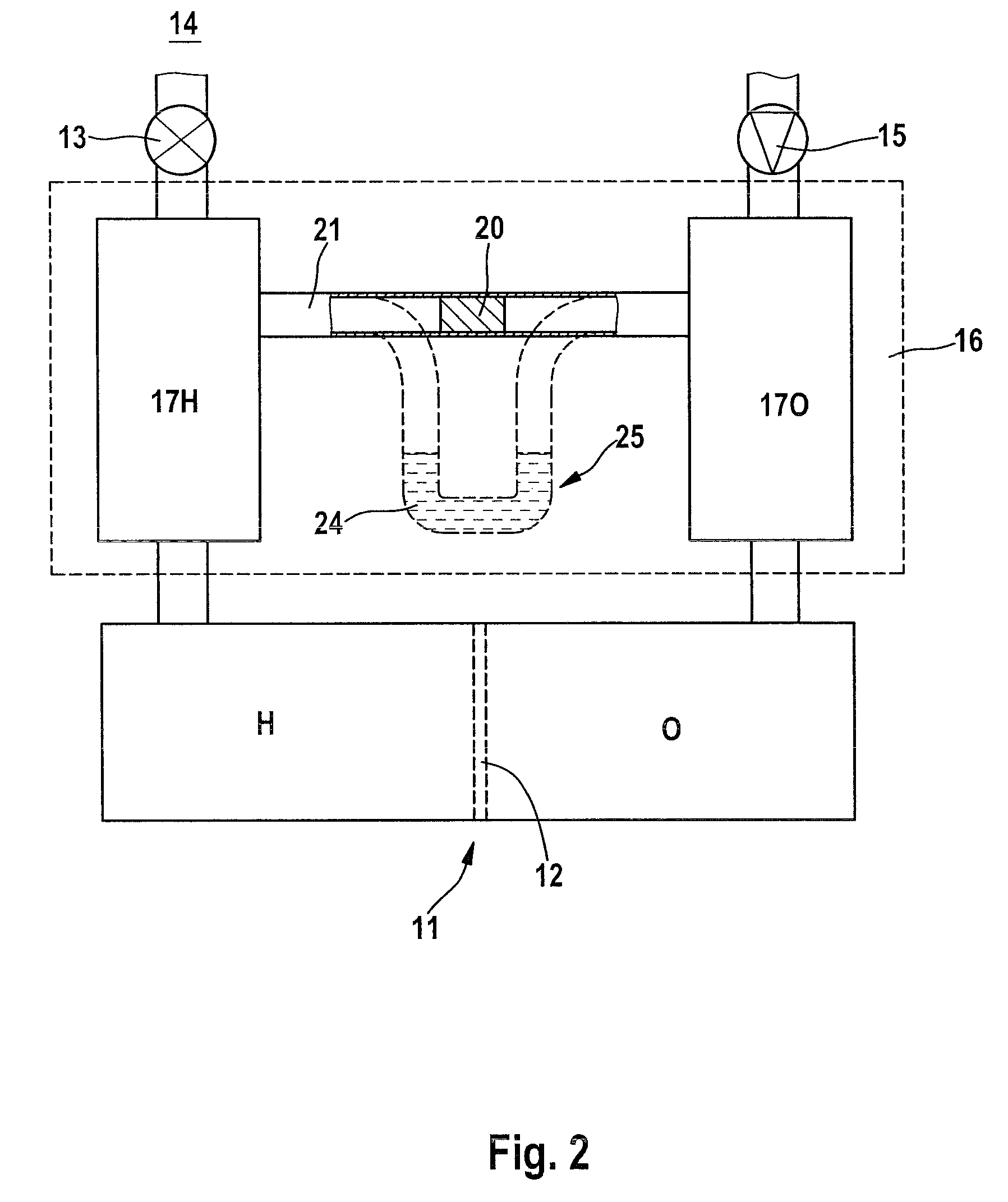
  • Figure 2
    Figure 2
  • Figure 3
    Figure 3
Patent Text Reader

Abstract

A pressure equalizing system (16) having two variable volume elements which interact with one another via a separating medium which can be deformed or can be moved as a function of the pressure difference, with a constant total volume, is positioned upstream of a fuel cell (11) in order to feed the fuel cell (11) with its raw-material gases (H, O). A pressure equalizing container (19) can be provided for this purpose, which is subdivided into two chambers (17H, 17O) by a separating wall (18) which can be deformed or can be moved as a function of the pressure difference; alternatively, two chambers (17H, 17O) are connected to one another by an equalizing channel (21) with a solid or liquid separating medium which can be moved therein as a function of the pressure difference. If the raw-material gas pressures are different, the separating medium is moved towards the chamber (17) with the lower gas pressure until a pressure equilibrium is achieved as a consequence of the corresponding change in the volume elements on both sides of the separating medium. In the fuel cell (11) which is fed from the chambers (17), its membrane (12), which is susceptible to fracture, therefore no longer has a destruction-critical dynamic pressure difference applied to it, without having to take control measures for this purpose in feed fittings for the raw-material gases.
Need to check novelty before this filing date? Find Prior Art

Description

BACKGROUND OF THE INVENTION

[0001] 1. Field of the Invention

[0002] The invention relates to a device and a method for the operation of a fuel cell with raw-material gases being fed to it on both sides of an electrolytic membrane thereof.

[0003] 2. Discussion of the Prior Art

[0004] By way of example, DE 10 2007 029 596 A1 describes that an electrolyte membrane, which is permeable for protons but is not permeable for electrons, keeps the two raw-material gases, which are fed in continuously, specifically the fuel supplied on the anode side (for example hydrogen) and the oxidant supplied on the cathode side (for example the oxygen contained in the surrounding area) separate from one another in a fuel cell. In particular, the membrane may be in the form of a thin polymer film (in a fuel cell of the PEM type) or in the form of a brittle oxide ceramic (in a fuel cell of the SOFC type).

[0005] The invention is based on the discovery that a very thin membrane such as this is highly susceptible to a...

Examples

Embodiment Construction

[0021]A fuel cell 11 is split in two by an electrolytic membrane 12. By way of example, on one side of the membrane 12, specifically the anode side, the cell 11 is fed with hydrogen H as fuel via a pressure-reducing valve 13 from a generator or from a reservoir 14 such as a compressed-gas cylinder and, opposite this, that is to say on the cathode side, the cell is fed for example with oxygen O as the oxidant (from a reservoir or) from the surrounding air, which is supplied by means of a compressor 15.

[0022]This raw-material gas feed is now, however, according to the invention no longer provided directly to the fuel cell 11 but via a pressure equalizing system 16, which is connected directly upstream of it, with two pressure equalizing chambers 17H, 17O which, in the case of FIG. 1, are separated from one another in a gas-tight manner by a separating wall 18, which can be deformed by pressure, as a function of the pressure difference, in a similar manner to a membrane, in a pressure-...