

Web service system, schedule execution apparatus and control method thereof
a scheduling and execution technology, applied in the field of scheduling execution apparatus, can solve the problems of difficult function enhancement, program complexity, lack of flexibility of the above-mentioned art, etc., and achieve the effect of more flexibility
- Summary
- Abstract
- Description
- Claims
- Application Information
AI Technical Summary
Benefits of technology
Problems solved by technology
Method used
Image

Examples
first exemplary embodiment
[0025
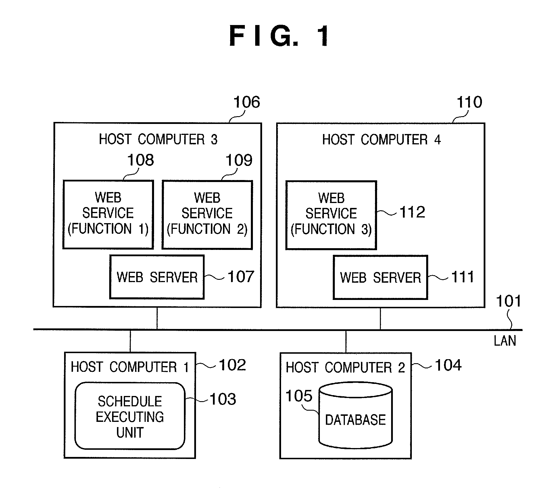
[0026]FIG. 1 is a diagram showing an exemplary configuration of a computer network in which a schedule execution apparatus according to a first embodiment of the present invention can be applied.
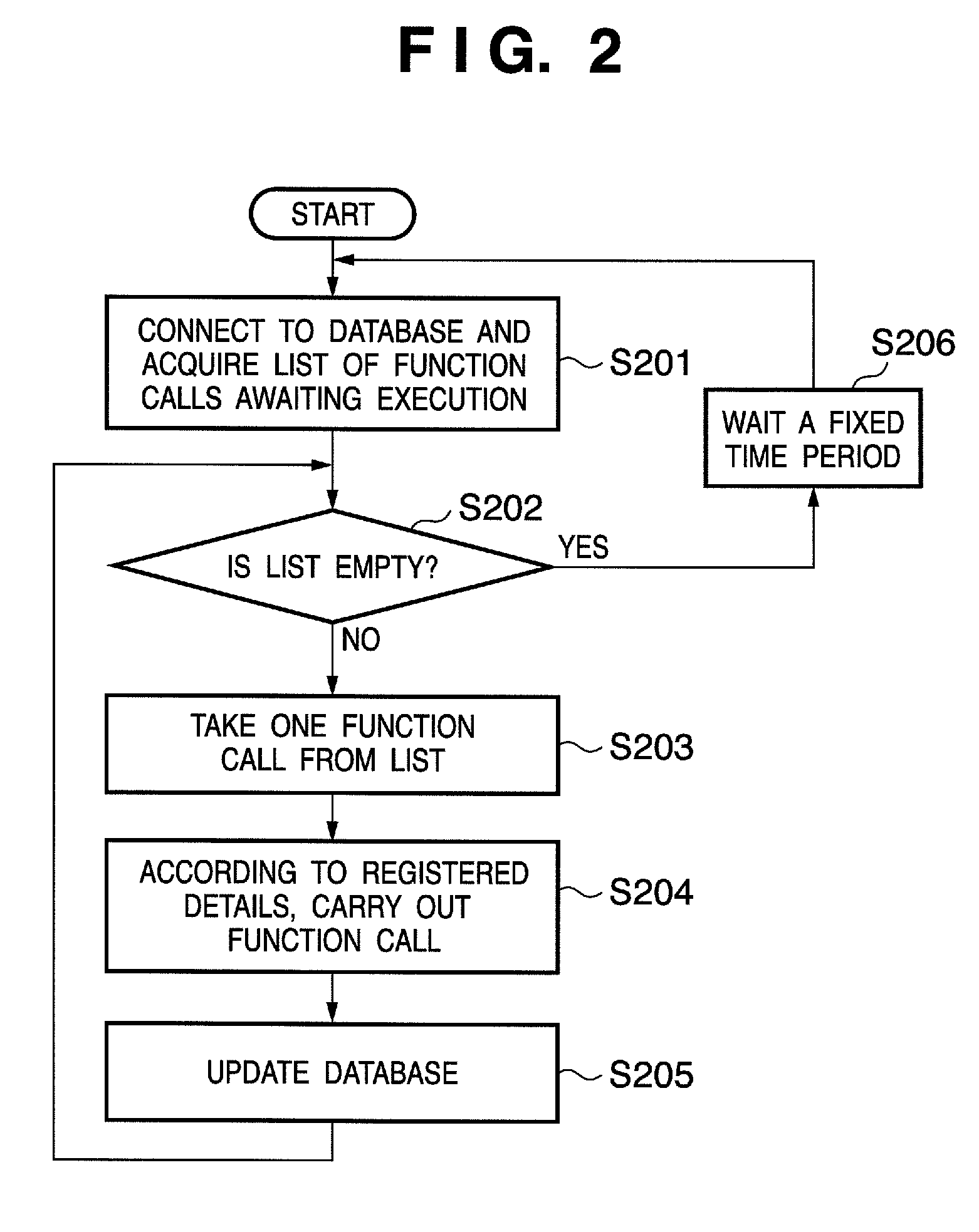
[0027]The computer network shown in FIG. 1 comprises a local area network (LAN) 101 to which are connected host computers 1 through 4 (102, 104, 106, 110). A schedule execution unit 103 for calling a function according to a specified schedule runs on host computer 1 (102), which functions as the schedule execution apparatus according to the present embodiment. As described above, the schedule execution unit 103 can be implemented as a program (for example, a resident program called either a daemon or a service) that runs on host computer 1 (102).
[0028]A database 105 operates in host computer 2 (104), and in the database 105 are stored details of the function that the schedule execution unit 103 calls and schedule information. The database 105 is implemented by a database application tha...
second exemplary embodiment
[0053
[0054]In the first embodiment, a description was given of a case in which the function call list that describes the process (schedule process) that is to be executed according to a schedule is registered in advance in the database 105. By contrast, in the present embodiment, the user can register new records in the function call list.
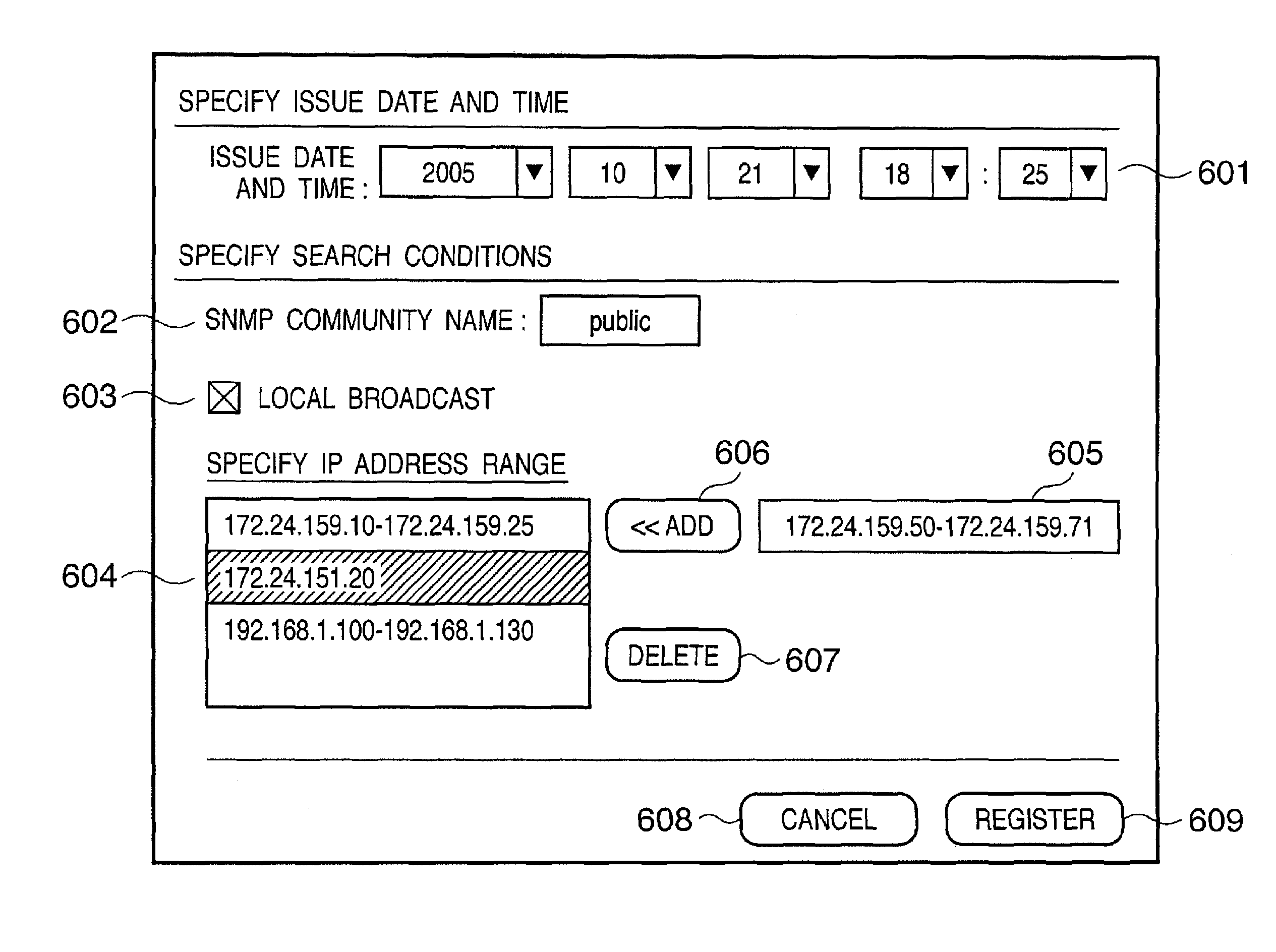
[0055]FIG. 5 is a diagram showing an exemplary configuration of a computer network according to a second embodiment of the present invention, in which constituent elements identical to those shown in FIG. 1 are assigned identical reference numerals. In this embodiment, a PC 502 that the user uses is provided in place of the host computer 4 (110) in the configuration shown in FIG. 1. The PC 502 may, for example, be an ordinary computer having the configuration described with reference to FIG. 11. The PC 502 functions as a registration apparatus for registering call information that controls the host computer 1 (102) which functions as the schedule e...
third exemplary embodiment
[0071
[0072]In some cases, a function that searches for a device, such as a computer or a printer, or a router or the like on the network 101 as in the example of the second embodiment, is started and the processing by the called function may not end within a short time period but instead can last several tens of minutes to several hours. With function calls using a Web service, it is desirable that execution results be returned to the Web service caller within a relatively short period of time (usually approximately several tens of seconds). As a result, when carrying out a time-consuming process utilizing a function call that uses a Web service, it is desirable to provide some countermeasure.
[0073]In the present embodiment, a time-consuming process is implemented using the above-described Web service call. In this embodiment as well as with the second embodiment, an example of a function call in the computer network shown in FIG. 5 is described.
[0074]FIG. 8 is a diagram showing an ...
PUM
 Abstract
Description
Claims
Application Information