Method and device for wireless communication in ue and base station

a wireless communication and wireless communication technology, applied in the direction of digital transmission, multi-antenna systems, transmission path sub-channel allocation, etc., can solve the problems of difficult to meet the demand for multi-antenna technology accuracy, control overhead, etc., to avoid performance loss, improve feedback efficiency, and avoid resource was

Active Publication Date: 2020-07-16
SHANGHAI LANGBO COMM TECH CO LTD
View PDF0 Cites 1 Cited by
  • Summary
  • Abstract
  • Description
  • Claims
  • Application Information

AI Technical Summary

Benefits of technology

[0067]In one sub-embodiment, the present disclosure has the following advantages compared with the conventional solution:
[0068]In Type II CSI feedback, the number of feedback beams is dynamically selected according to the number of layers fed back; That is to avoid the waste of resources caused by too many beams fed back when the number of layers is small, and to avoid the performance loss caused by feedback of insufficien...

Problems solved by technology

As the quantity of antenna equipped on the base station side increases, the accuracy of implicit CSI is difficult to meet the demand for multi-antenna technology such as MU-MIMO (multi-user mu...

Method used


Image

  • Method and device for wireless communication in ue and base station
  • Method and device for wireless communication in ue and base station
  • Method and device for wireless communication in ue and base station

Examples


embodiment 1

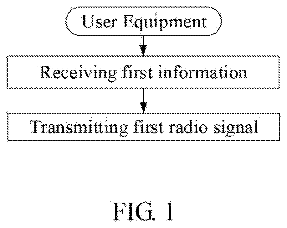
[0099]Embodiment 1 illustrates a flow chart of a first information and a first radio signal, as shown in FIG. 1.

[0100]In Embodiment 1, the user equipment in the disclosure receives the first information, and transmits the first radio signal. Wherein the first radio signal carries a first bit block, the first bit block being used to determine R, L first vectors and R second type parameter group(s); the R is used to determine the L from P candidate integers; the first information is used to determine the P candidate integers; each second type parameter group of the R second type parameter group(s) comprises L2 second type parameters, the L2 being equal to the L multiplied by 2; R3 second type parameter group(s) in the R second type parameter group(s) is(are) respectively used with the L first vectors to generate R3 merge vector(s); the P is a positive integer greater than 1; the R is a positive integer; the R3 is a positive integer not greater than the R; the P candidate integers are ...

embodiment 2

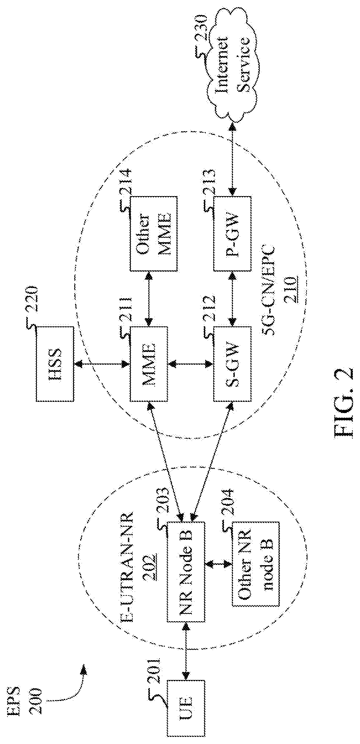
[0146]Embodiment 2 illustrates a schematic diagram of a network architecture, as shown in the figure.

[0147]FIG. 2 illustrates a network architecture 200 of LTE (Long-Term Evolution), LTE-A (Long-Term Evolution Advanced) and future 5G systems. The LTE network architecture 200 may be referred to as an EPS (Evolved Packet System) 200. The EPS 200 may include one or more UEs (User Equipment) 201, an E-UTRAN-NR (Evolved UMTS Terrestrial Radio Access Network—New Wireless) 202, a 5G-CN (5G-CoreNetwork, 5G core network) / EPC (Evolved Packet Core) 210, a HSS (Home Subscriber Server) 220 and Internet Service 230. Wherein the UMTS corresponds to the Universal Mobile Telecommunications System. The EPS 200 may be interconnected with other access networks, but for the sake of simplicity, these entities / interfaces are not shown. As shown in the FIG. 2, the EPS 200 provides packet switching services. Those skilled in the art would readily appreciate that the various concepts presented throughout thi...

embodiment 3

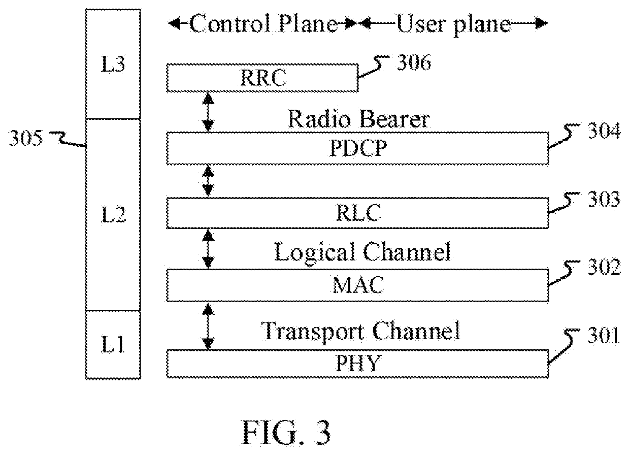
[0154]Embodiment 3 illustrates a schematic diagram of a radio protocol architecture of a user plane and a control plane according to an embodiment of the present disclosure, as shown in FIG. 3.

[0155]FIG. 3 is a schematic diagram illustrating an embodiment of a radio protocol architecture for a user plane and a control plane, and FIG. 3 illustrates a radio protocol architecture for the UE and gNB in three layers: layer 1, layer 2 and layer 3. Layer 1 (L1 layer) is the lowest layer and implements various PHY (physical layer) signal processing functions. The L1 layer will be referred to herein as PHY 301. Layer 2 (L2 layer) 305 is above PHY 301 and is responsible for the link between the UE and the gNB through PHY 301. In the user plane, L2 layer 305 comprises a MAC (Medium Access Control) sub-layer 302, RLC (Radio Link Control) sub-layer 303 and PDCP (Packet Data Convergence Protocol) sub-layer 304, and these sub-layers terminate at the gNB on the network side. Although not illustrate...


PUM


Abstract

The present disclosure discloses a method and device for wireless communication in a user equipment and base station. The user equipment receives first information and sends first radio signal. The first radio signal carries a first bit block, the first bit block being used to determine R, L first vectors and R second type parameter group(s); the R is used to determine the L from P candidate integers; the first information is used to determine the P candidate integers; each second type parameter group of the R second type parameter group(s) comprises L2 second type parameters, the L2 being equal to the L multiplied by 2; R3 second type parameter group(s) in the R second type parameter group(s) is(are) respectively used with the L first vectors to generate R3 merge vector(s); the P is a positive integer greater than 1; the R (greater than R3) and R3 are positive integers.

Description

CROSS-REFERENCE TO RELATED APPLICATION[0001]This application is a continuation of International Application No. PCT / CN2019 / 092793, filed on Jun. 25, 2019, claiming the priority benefit of Chinese Application No. 201810693236.6, filed on Jun. 29, 2018, the full disclosure of which is incorporated herein by reference.BACKGROUNDTechnical Field[0002]The present disclosure relates to a method and device in a wireless communication system, particularly to a method and device in a wireless communication system that supports uplink channel state information feedback.Related Art[0003]In a wireless communication system that supports multi-antenna transmission, it is a common technique for a UE (User Equipment) to feedback CSI (Channel Status Information) to assist the base station in performing multi-antenna processing. In the traditional 3GPP-3rd Generation Partner Project cellular network system, the implicit CSI (Channel State Information) feedback is supported. The implicit CSI includes C...

Claims


Application Information

Patent Timeline
IPC IPC(8): H04B7/06H04B7/08H04L5/00
CPCH04B7/0865H04L5/0051H04B7/0663H04B7/0634H04B7/0626H04B7/0639H04B7/0632H04B7/0456H04L5/0055H04B7/0478
Inventor WU, KEYINGZHANG, XIAOBOYANG, LIN
Owner SHANGHAI LANGBO COMM TECH CO LTD
Why Eureka
Try Eureka