Jaw thrust device

a thrust device and thrust device technology, applied in the field of patient airway maintenance, can solve the problems of limiting the ability of medical practitioners to perform procedures on the patient's head and neck, blocking the airway of the patient, and not addressing other parts of the patient's airway

Active Publication Date: 2012-06-05
HAWORTH RANDAL
View PDF21 Cites 28 Cited by
  • Summary
  • Abstract
  • Description
  • Claims
  • Application Information

AI Technical Summary

Problems solved by technology

The jaw thrust is a technique used on patients in a supine position to open the patient's trachea (airway), which has become blocked by the backward movement of the lower jaw (mandible) relative to the rest of the patient's skull, which in turn can cause the patient's airway to be blocked.
Numerous devices have in the past been proposed for assisting in this procedure, which have been met with limited acceptance.
Among the difficulties with prior devices is that many secure the patient's head to the device and / or to the surface (e.g., an operating table) on which the patient is positioned, which limits the medical practitioner's ability to perform procedures on the patient's head and neck.
Additionally, many prior devices address only the relative position of the mandible and the associated position of the patient's tongue, and do not address other portions of the patient's airway.

Method used


Image

  • Jaw thrust device
  • Jaw thrust device
  • Jaw thrust device

Examples


second embodiment

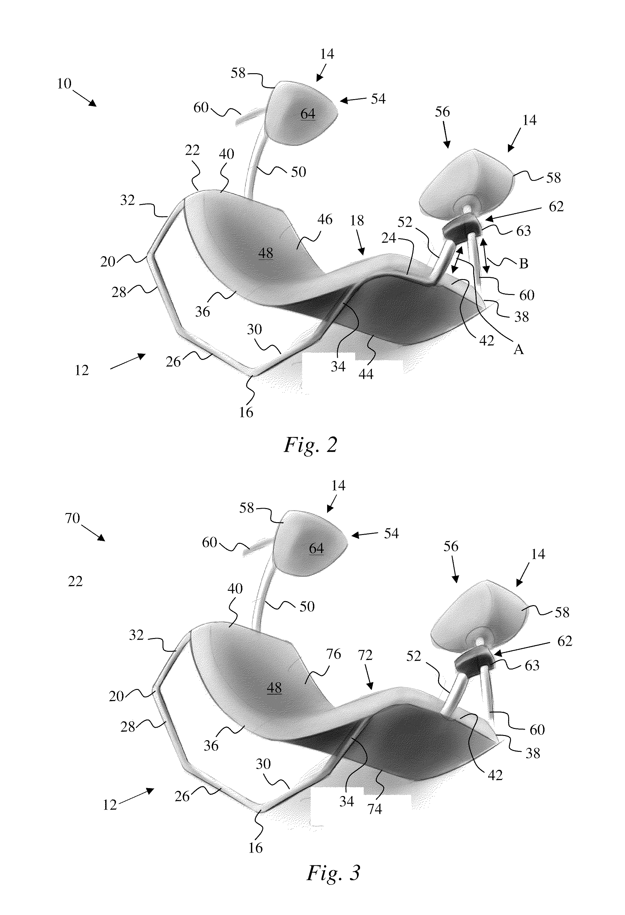
[0067]FIG. 3 illustrates the device 1 schematically represent in FIG. 1. In this embodiment, a device 70 can be substantially identical to the device 10 of FIG. 2, except as noted below. Accordingly, substantially identical features of the device 70 are denoted by the same references numerals as used for the device 10 of a FIG. 2.

[0068]The device 70 can include a neck pad 72 that can be configured to internally receive the pad supports (not visible—see pad supports 22, 24 of FIG. 2, for example) of the frame 16 and a portion of the mounting arms 50, 52. In particular, the pad supports can extend within the neck pad 72 between the backing 74 and the cushion 76 of the neck pad 72. Thus, the neck pad 72 can be connected to the frame 16.

third embodiment

[0069]FIG. 4 illustrates the device 1 schematically represent in FIG. 1. In this embodiment, a device 80 can be substantially identical to the device 10 of FIG. 2, with any exceptions and / or modifications noted below. Accordingly, substantially identical features of the device 80 are denoted by the same references numerals as used for the device 10 of a FIG. 2.

[0070]The device 80 can include a base 82. The base 82 can include a frame 84 and a neck pad 86. The neck pad 86 can include a backing 88 and a cushion 90. The backing 88 and the cushion 90 can include substantially all the features of the backing 44 and the cushion 46 described with reference to the device 10 of FIG. 2. In this exemplary embodiment, the backing 88 of the neck pad 86 can be integrally formed with the frame 84 to define a single, homogenous component. The cushion 90 of the neck pad 86 can be affixed to the backing 88 in any manner described above with reference to FIG. 2.

[0071]The frame 82 can include a polygon...

fourth embodiment

[0086]FIGS. 5-9 illustrate the device 1 schematically represent in FIG. 1. In this embodiment, a device 120 can be substantially identical to the device 10 of FIG. 2, with any exceptions and / or modifications noted below. Description of the device 120 is provided with specific reference to FIGS. 5 and 6.

[0087]The device 120 can include a base 122 and a jaw support 124 that can engage and support a patient's neck and mandible, respectively, as described above with reference to the device 10 of FIG. 2.

[0088]The base 122 can include a frame 126 and a neck pad 128. The jaw support 124 can be connected to the frame 126, as will be described in detail below. The neck pad 128 can be merely placed onto the frame 126 or the neck pad 128 can be positively connected to the frame 126. If the neck pad 128 is positively connected to the frame 126, then the neck pad 128 can either be removably connected or permanently connected to the frame 126. Details of the engagement of the frame 126 by the nec...


PUM


Abstract

A pair of pads is held against the remus of a patient's jaw, to prevent the jaw from slipping back and causing an airway obstruction, while the patient's neck is hyperextended to also cause the patient's airway to stay open. A device including the adjustable jaw pads as well as a triangularly shaped portion over which the patient's neck rests is not required to be attached to the surface on which the patient is lying, and permits the patient to be rolled on either side while still maintaining the patency of the patient's airway.

Description

[0001]This application claims priority under 35 U.S.C. §119 to U.S. Provisional application No. 61 / 076,757, filed 30 Jun. 2008, entitled “Jaw Thrust Device and Method”, the entirety of which is incorporated by reference herein.BACKGROUND[0002]1. Field of Endeavor[0003]The present invention relates to devices, systems, and processes useful in patient airway maintenance, and more specifically to devices and methods that perform a jaw thrust.[0004]2. Brief Description of the Related Art[0005]The jaw thrust is a technique used on patients in a supine position to open the patient's trachea (airway), which has become blocked by the backward movement of the lower jaw (mandible) relative to the rest of the patient's skull, which in turn can cause the patient's airway to be blocked. The practitioner typically uses their thumbs to physically push the posterior (back) aspects of the mandible forward and into a position in which the airway is no longer blocked. When the mandible is displaced fo...

Claims


Application Information

Patent Timeline
Patent Type & Authority Patents(United States)
IPC IPC(8): A61G15/00A61F5/00A61H5/00A47B7/02
CPCA61F5/055A61G13/1215A61F5/05891A61G13/129
Inventor HAWORTH, RANDALSTONE, CORBETT W.
Owner HAWORTH RANDAL
Why Eureka
Try Eureka