
Set of artificial teeth having convex adjustment surface

a technology of adjustment surface and artificial teeth, which is applied in the field of sets of artificial teeth, can solve the problems of difficult to predict such distortion, difficult to obtain optimal occlusion state for chewing food, and often improper occlusion state, so as to improve occlusion state and easily correct faulty occlusion

Active Publication Date: 2012-06-12
SHOFU INC
View PDF6 Cites 0 Cited by
  • Summary
  • Abstract
  • Description
  • Claims
  • Application Information

AI Technical Summary

Benefits of technology

The present invention provides a set of artificial teeth that can easily adjust their occlusion without requiring high precision in arrangement. The artificial teeth have a convex adjustment surface and an opposing surface that is in point or line contact with the adjustment surface. This small contact area allows for significant changes in the occlusion state by scaling the adjustment surface or the opposing surface. The adjustment surface can be a spherical, cylindrical, or conical surface, and the opposing surface can be a flat, spherical, or conical surface. The adjustment surface and the opposing surface can be inclined at various angles to each other. This configuration allows for easy adjustment of the occlusion state even when the artificial teeth are not perfectly aligned. The set of artificial teeth can be used for all the molar teeth in a dental prosthetic appliance.

Problems solved by technology

However, even if highly functional artificial teeth can be produced at a designing stage, artificial teeth that are actually produced do not always have shapes and arrangement as designed, so that an occlusion state often becomes improper.
When the artificial teeth of the plate dentures are incompletely arranged, it is not possible to obtain an optimal occlusion state for sufficiently chewing food.
It is extremely difficult to predict such a distortion and arrange the artificial teeth in maxillary and mandibular arches so as to gain the arrangement, as designed, at the end.
In a case where there are still remaining teeth or the like, it is more difficult to arrange the artificial teeth at optimal positions.
Therefore, the artificial teeth often have to be displaced from the optimal positions.

Method used


Image

  • Set of artificial teeth having convex adjustment surface
  • Set of artificial teeth having convex adjustment surface
  • Set of artificial teeth having convex adjustment surface

Examples


Embodiment Construction

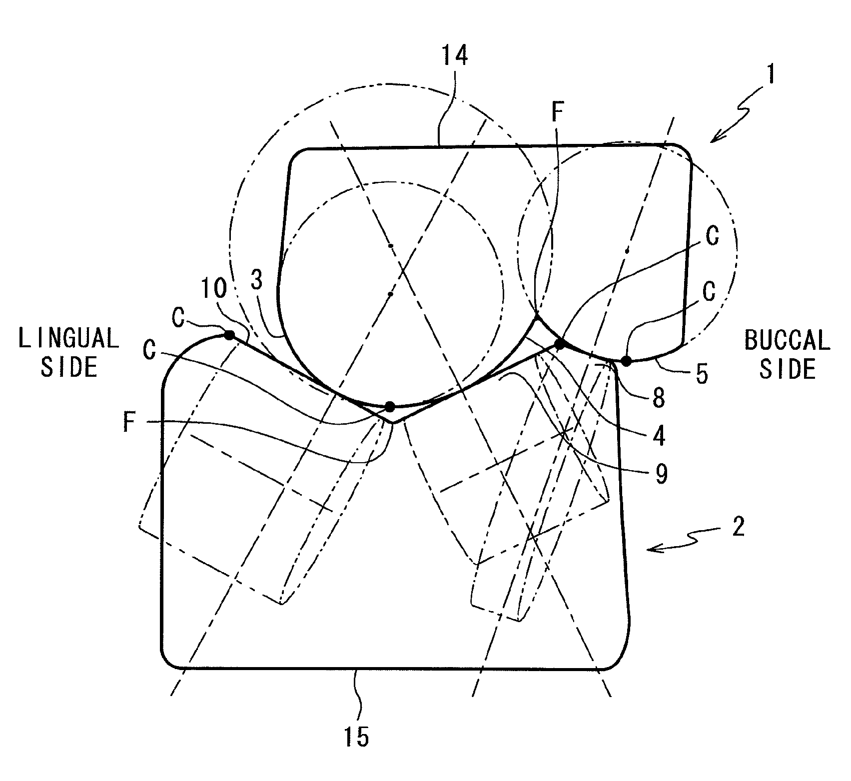
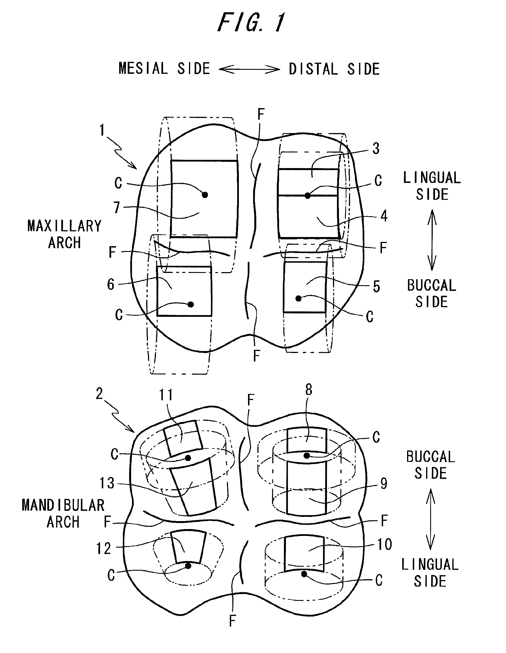
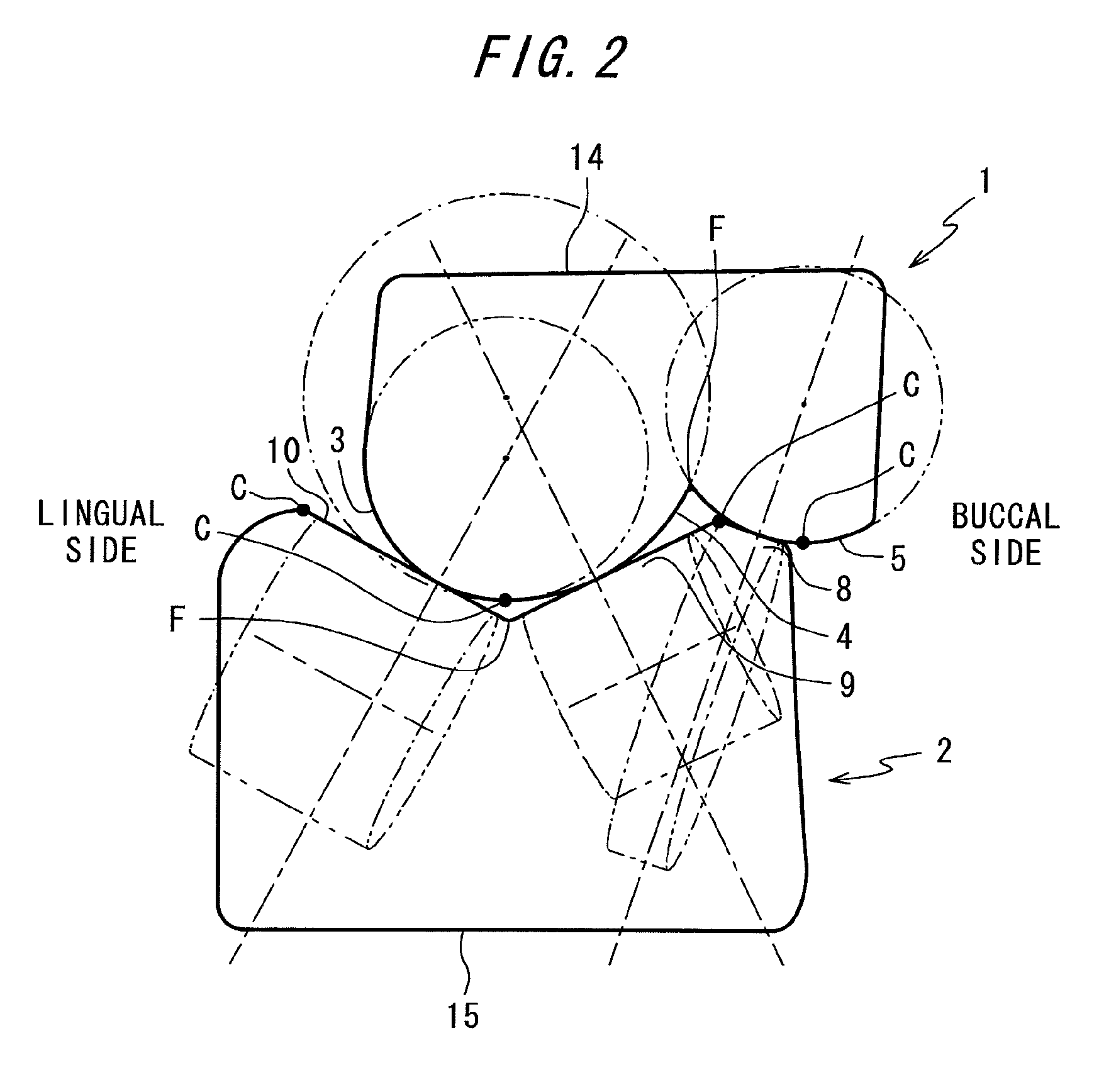
[0027]FIG. 1 shows occlusal surfaces of a set of artificial teeth according the embodiment of the present invention. This set of artificial teeth includes artificial maxillary and mandibular second molar teeth 1 and 2 that occlude with each other.

[0028]The artificial maxillary molar tooth 1 has convex cylindrical surfaces 3, 4, 5, 6 and 7 including four cusps C. The cylindrical surfaces 3, 4, 5, 6 and 7 serve as part of outer surfaces of cylinders (shown by double dotted lines) having axes which extend in a substantially mesial direction, respectively.

[0029]Occlusal surfaces around the cylindrical surfaces 3, 4, 5, 6 and 7 are formed of free form surfaces. Although outlines of the cylindrical surfaces 3, 4, 5, 6 and 7 are shown in the figure for easy understanding, the occlusal surfaces are connected to the surrounding occlusal surfaces with gentle sloping. The outlines of the cylindrical surfaces 3, 4, 5, 6 and 7 (borders with the surrounding occlusal surfaces) are not necessarily ...


PUM


Abstract

A set of artificial teeth allows for easy occlusion adjustment without high precision in arrangement. One of a pair of occluding upper and lower artificial molar teeth has convex adjustment surfaces which are formed of a spherical surface, a cylindrical surface or a conical surface on an occlusal surface thereof, and the other of the pair of artificial molar teeth has opposing surfaces which are formed of a flat surface, a spherical surface, a cylindrical surface or a conical surface in point contact or line contact with the adjustment surfaces on an occlusal surface thereof.

Description

BACKGROUND OF THE INVENTION[0001]1. Field of the Invention[0002]The present invention relates to a set of artificial teeth including at least a pair of upper and lower artificial molar teeth.[0003]2. Description of the Related Art[0004]With too much awareness of natural teeth, conventional artificial teeth are designed focusing on reproducing shapes of the natural teeth. In recent years, various shapes of artificial teeth have been proposed in order to produce the artificial teeth focusing on functions. Those shapes are elaborately designed so as to exert proper functions when the artificial teeth are precisely arranged.[0005]However, even if highly functional artificial teeth can be produced at a designing stage, artificial teeth that are actually produced do not always have shapes and arrangement as designed, so that an occlusion state often becomes improper. An oral cavity is different between individual patients, and the size of the oral cavity, height and angles of residual rid...

Claims


Application Information

Patent Timeline
Patent Type & Authority Patents(United States)
IPC IPC(8): A61C13/00
CPCA61C13/097
Inventor KADOBAYASHI, YUSEI
Owner SHOFU INC
Learn More