Magnetic recording head and magnetic recording method

a recording head and magnetic technology, applied in the field of magnetic recording head and magnetic recording method, can solve the problems of insufficient suppression of pole erasure, inability to enhance writing efficiency, remarkable insignia, etc., and achieve the effect of reducing the fixing portion of the pole magnetization

Active Publication Date: 2012-06-12
KK TOSHIBA
View PDF24 Cites 1 Cited by
  • Summary
  • Abstract
  • Description
  • Claims
  • Application Information

AI Technical Summary

Benefits of technology

[0014]Another aspect of the present invention relates to a magnetic recording method using a magnetic recording head including; a main magnetic pole containing a ferromagnetic layer; a main magnetic pole-magnetization fixing portion containing an antiferromagnetic layer in contact with at least one side surface of the main magnetic pole; a heater for the main magnetic pole; and a magnetic field generator for generating a magnetic field so as to direct a magnetization of the main magnetic pole in one direction, including: heating, in writing, the main magnetic pole with the heater so that a magnetic interaction between the main magnetic pole and the main magnetic pole-magnetization fixing portion can be decreased; and generating, in the writing, the magnetic field with the magnetic generator so that the magnetization of the main magnetic pole can be directed perpendicular to a surface of a recording medium by the magnetic field.

Problems solved by technology

However, the instability in the signals becomes remarkable due to heat fluctuation as the recording density becomes high so that the longitudinal magnetic recording method is substituted with a perpendicular magnetic recording method because the longitudinal magnetic recording method can maintain the signals stably.
In order to prevent the Pole erasure, such an attempt as devising the shape of the main magnetic pole 11 is made, but the writing efficiency can not be enhanced sufficiently and the Pole erasure can not be suppressed sufficiently because the writing efficiency is traded off with the Pole erasure.

Method used


Image

  • Magnetic recording head and magnetic recording method
  • Magnetic recording head and magnetic recording method
  • Magnetic recording head and magnetic recording method

Examples


first embodiment

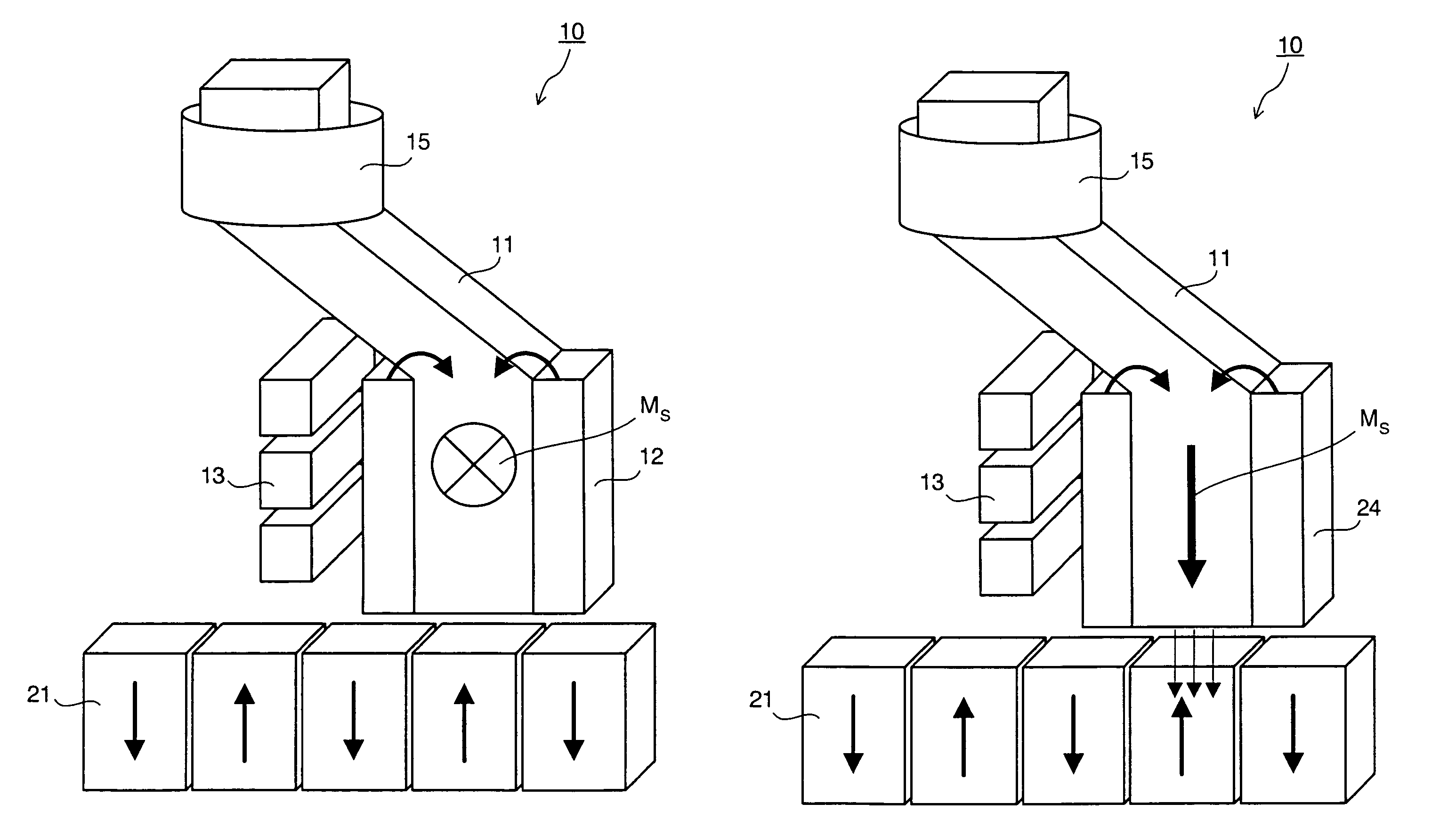
[0039]FIGS. 6 and 7 relate to a structural view showing a magnetic recording head according to a first embodiment. FIG. 6 shows the non-writing state of the magnetic recording head and FIG. 7 shows the writing state of the magnetic recording head. Like or corresponding components are designated by the same reference numerals throughout the drawings.

[0040]In FIGS. 6 and 7, the magnetic recording head 10 includes the main magnetic pole 11 and the main magnetic pole-magnetization fixing portions 24 in contact with both sides of the main magnetic pole 11. The main magnetic pole 11 is constituted from a ferromagnetic layer made of FeCo-based alloy which can exhibit a larger recording magnetic field due to the larger saturated magnetization thereof. The intensity of the magnetization Ms of the alloy can be varied by controlling the composition of the alloy. The FeCo-based alloy may contain a third element such as Cr as occasion demands. When the FeCo-based alloy contains the third element...

second embodiment

[0050]FIGS. 9 and 10 relate to a structural view showing a magnetic recording head according to a second embodiment.

[0051]In FIGS. 9 and 10, the magnetic recording head 10 includes the main magnetic pole 11 and the main magnetic pole-magnetization fixing portions 24 in contact with both sides of the main magnetic pole 11. The main magnetic pole 11 is constituted from a ferromagnetic layer made of FeCo-based alloy which can exhibit a larger recording magnetic field due to the larger saturated magnetization thereof. The intensity of the magnetization Ms of the alloy can be varied by controlling the composition of the alloy. The FeCo-based alloy may contain a third element such as Cr as occasion demands. When the FeCo-based alloy contains the third element, the magnetization Ms of the main magnetic pole 11 is decreased but the corrosion-resistance of the main magnetic pole 11 can be enhanced.

[0052]The main magnetic pole-magnetization fixing portions 24 are constituted from antiferromag...

third embodiment

[0063]In this embodiment, the material of the antiferromagnetic layer constituting the main magnetic pole-magnetization fixing portion 24 of the magnetic recording head in the first embodiment and the second embodiment is changed. In this embodiment, namely, the antiferromagnetic layer is made of FeRh alloy. FIG. 11 is a graph showing the temperature dependence of the FeRh alloy. The FeRh alloy exhibits magnetic phase transition around room temperature, antiferromagnetic property below room temperature and ferromagnetic property over room temperature. The temperature of the magnetic phase transition can be varied within a temperature range of several ten degrees Celsius by controlling the composition of the FeRh alloy and the forming method of the FeRh alloy.

[0064]If the antiferromagnetic layer of the main magnetic pole-magnetization fixing portion 24 is made of the FeRh alloy, the following operation can be conducted: Namely, the antiferromagnetic layer functions as an antiferromag...


PUM

PropertyMeasurementUnit
temperatureaaaaaaaaaa
lengthaaaaaaaaaa

Abstract

A magnetic recording head includes: a main magnetic pole containing a ferromagnetic layer; a main magnetic pole-magnetization fixing portion containing an antiferromagnetic layer in contact with at least one side surface of the main magnetic pole; a heater for heating at least the main magnetic pole so that a magnetic interaction between the main magnetic pole and the main magnetic pole-magnetization fixing portion can be decreased; and a magnetic field generator for generating a magnetic field so as to direct a magnetization of the main magnetic pole in one direction.

Description

CROSS-REFERENCE TO RELATED APPLICATIONS[0001]This application is based upon and claims the benefit of priority from the prior Japanese Patent Applications No. 2007-094475, filed on Mar. 30, 2007 and 2007-141827, filed on May 29, 2007; the entire contents of which are incorporated herein by reference.BACKGROUND OF THE INVENTION[0002]1. Field of the Invention[0003]The present invention relates to a newly structured magnetic recording head and a magnetic recording method utilizing the magnetic recording head.[0004]2. Description of the Related Art[0005]Recently, a longitudinal magnetic recording method has been employed as a magnetic recording method. In the longitudinal magnetic recording method, the magnetizations relating to signals to be recorded are directed in parallel in the plane of a recording medium. However, the instability in the signals becomes remarkable due to heat fluctuation as the recording density becomes high so that the longitudinal magnetic recording method is sub...

Claims


Application Information

Patent Timeline
Patent Type & Authority Patents(United States)
IPC IPC(8): G11B5/31G11B5/465
CPCG11B5/02G11B5/314G11B2005/0002G11B5/1278G11B5/3163
Inventor YUASA, HIROMITAGUCHI, TOMOKOFUKUZAWA, HIDEAKI
Owner KK TOSHIBA
Why Eureka
Try Eureka