Router

a router and router technology, applied in the field of routers, can solve the problems of reducing cutting precision, affecting the smooth upward and downward movement of the router, and affecting the ease of operation of the router, so as to reduce or eliminate the backlash, improve the ease of operation, and improve the cutting precision

Active Publication Date: 2012-07-03
MAKITA CORP
View PDF19 Cites 0 Cited by
  • Summary
  • Abstract
  • Description
  • Claims
  • Application Information

AI Technical Summary

Benefits of technology

[0011]According to some embodiments of the present invention, the use of a linear ball bearing in at least one of the bushings renders the main body smoothly operable upward and downward even with one hand, and serves to reduce or eliminate a backlash between the guide shafts and the bushings provided in the main body, so that the ease of operation and the cutting precision can be improved.
[0012]In a particular embodiment where a preload is horizontally applied to the linear ball bearing, the backlash between the guide shafts and the bushings provided in the main body can be suppressed more effectively. Consequently, the operation for moving the main body upward and downward can be carried out more smoothly and the cutting precision can be improved more greatly.

Problems solved by technology

As a result, a friction between the columns and the bushings would possibly hamper a smooth upward and downward movement of the main body in some instances.
In particular, when an operator attempts to lower the main body with one hand gripping one of the handles, the main body would be swayed and blocked from moving any longer, which would thus impair the ease of operation of the router.
Furthermore, the presence of the backlash structurally inevitably produced between the columns and the bushings would disadvantageously reduce the cutting precision.

Method used


Image

  • Router
  • Router
  • Router

Examples


Embodiment Construction

[0018]Exemplary embodiments of the present invention will be described hereinafter with reference to the accompanying drawings.

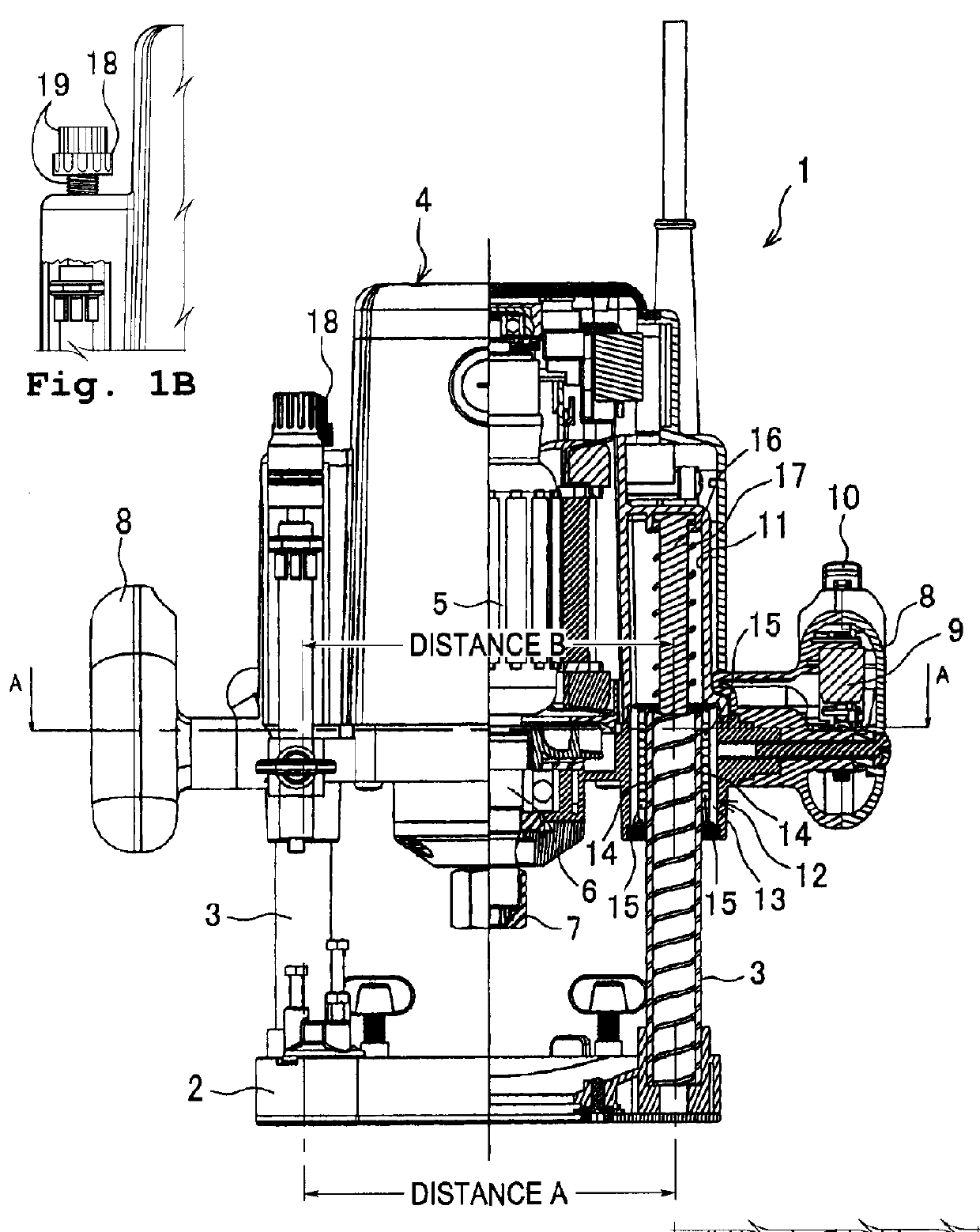
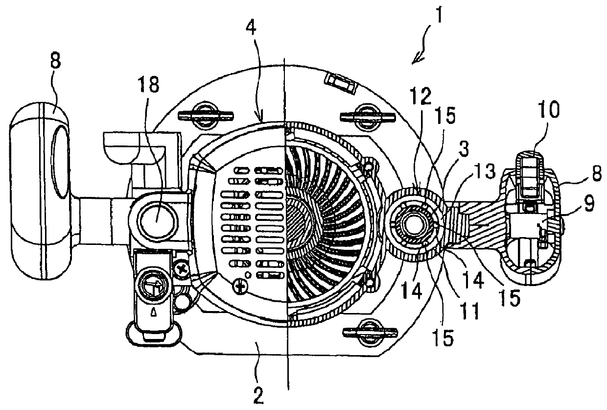
[0019]In FIG. 1, one example of a router consistent with the present invention is illustrated with a right-side half thereof shown in a vertical section. Referring now to FIGS. 1 and 2, a router 1 comprises a disk-shaped base 2 having an opening at its center, a pair of guide pipes 3 (which serves as a pair of guide shafts) spaced apart laterally and stood upright on an upper surface of the base 2, and a main body 4 coupled to the both guide pipes 3 in such a manner that the main body 4 is allowed to be moved upward and downward. A motor 5 is housed in the main body 4, with its output shaft disposed at a bottom side of the motor, and a spindle 6 coupled to the output shaft projects downwardly from a bottom side of the main body. At a lower end of the spindle 6 a chuck 7 is provided to which a tool (not shown) can be mounted in a detachable manner. Denoted by...


PUM

PropertyMeasurementUnit
frictionaaaaaaaaaa
biasing forceaaaaaaaaaa
horizontal distancesaaaaaaaaaa

Abstract

A router is provided, which includes a main body with a pair of coupling hollows, and a base having a pair of guide shafts standing on. Each of the pair of coupling hollows has an opening facing downward through which a corresponding guide shaft is inserted. A linear ball bearing which serves as a bushing to support a corresponding guide shaft is provided in a lower portion of at least one of the coupling hollows. With this linear ball bearing, the guide shaft can be slid in the coupling hollow smoothly.

Description

BACKGROUND OF THE INVENTION[0001]This application claims the benefit of Japanese Patent Application Number 2007-285435 which were filed on Nov. 1, 2007, the entirety of which is incorporated by reference.[0002]1. Field of the Invention[0003]This invention relates to a router which comprises a base, a pair of guide shafts stood on the base and a main body mounted with a tool pointed downward at an underside thereof, the main body being coupled to the pair of guide shafts in such a manner that the main body is movable upward and downward.[0004]2. Description of Related Art[0005]In the router, typically, for example as disclosed in Japanese Laid-Open Patent Application, Publication No. 6-328402, a pair of columns (guide shafts) are stood on a disk-shaped base, and a main body having a motor housed therein and a downward-pointing tool mounted on an underside thereof is provided with sleeve-like bushings in which the columns can be loosely fitted. The bushings of the main body support th...

Claims


Application Information

Patent Timeline
Patent Type & Authority Patents(United States)
IPC IPC(8): B23C1/20B27C5/10
CPCB27C5/10Y10T409/306608
Inventor KIMURA, TAKUJIUTSUNO, ATSUSHI
Owner MAKITA CORP
Why Eureka
Try Eureka