Inertial torque reaction management with selectively engageable counter rotating component

a technology of inertial torque and reaction management, which is applied in the direction of machines/engines, mechanical equipment, etc., can solve the problems of reducing system responsiveness, unwanted noise and vibration in the passenger compartment of the vehicle, and increasing mass also increasing weight, so as to reduce or eliminate the torque reaction, reduce the adverse impact of system performance and response, and improve performance

Inactive Publication Date: 2007-02-20
FORD GLOBAL TECH LLC
View PDF25 Cites 7 Cited by
  • Summary
  • Abstract
  • Description
  • Claims
  • Application Information

AI Technical Summary

Benefits of technology

[0008]In one embodiment, the present invention uses a selectively engageable counter-rotating inertia installed within the engine sump to reduce or eliminate the inertial torque reaction otherwise associated with angular acceleration / deceleration of a rotating mass on stationary structure or mounting components. The counter rotating inertia may be provided by a simple inertial mass or by an electrical, hydraulic, or pneumatic machine functioning as an integral starter / generator (ISG). The system and method include a device to mechanically and / or electrically couple the counter-rotating inertia to one or more forward rotating components. The device may be implemented by a plurality of drive components such as gears, belts, chains and sprockets, or any similar device used to couple to a torque-carrying component of an internal combustion engine such as the crankshaft. A scissors type gear or other feature to reduce or eliminate backlash to closely couple the counter-rotating component(s) and prevent gear rattle may also be used.
[0009]Various embodiments of the invention use sliding type bearings, springs, and flanges, or a plurality of locking devices such as a hydraulically actuated pin that can engage and disengage to selectively couple and uncouple the counter-rotating inertia when desired. Appropriate selection of the drive ratio(s) across the coupling device to drive the counter-rotating inertia faster than the forward rotating inertia allows the counter-rotating inertia to be smaller in size and mass, yet still substantially match the effective inertia of the forward rotating components.
[0011]The present invention provides a number of advantages. For example, the present invention provides systems and methods for managing inertial torque reaction using a selectively engageable counter-rotating inertia to reduce or eliminate the torque reaction on the powertrain structure and improve performance with respect to noise, vibration, and harshness (NVH). Selectively disengaging the counter-rotating inertia at higher engine rotational speeds reduces any adverse impact on system performance and response, reduces any associated friction and wear of the coupling device and counter-rotating inertia, and facilitates use of a positive speed differential to increase speed of the counter-rotating inertia relative to the crankshaft so that effective inertia can be substantially matched with smaller and less massive components. Rotating an integral starter / generator in a direction opposite to that of the engine crankshaft obviates the need for additional non-functional components or mass to generate balancing inertia. This reduces any adverse impact on powertrain weight, responsiveness, and overall performance and fuel economy relative to conventional solutions that add components solely for balancing or canceling torque reactions associated with rotating inertia. Additionally, an integral starter / generator provided according to the teachings of the present invention may be used to provide vehicle launch assist, engine cranking (eliminating the conventional starter motor), and regenerative braking without increasing powertrain length associated with a conventionally mounted ISG. The present invention may allow variable displacement engines to idle and drive at low engine speeds with fewer than all of the cylinders firing without unacceptable NVH. Also, the reduced or limited inertial torque reaction on the stationary powertrain structure should reduce noise, vibration, and harshness (NVH) with the uneven firing intervals that occur when an 8-cylinder engine operates in a reduced or variable displacement mode with 3, 5, 6, or 7 firing cylinders, for example.

Problems solved by technology

This vibration of the stationary structure passes vibration through the resilient mounts into the vehicle chassis, and may result in unwanted noise and vibration within the vehicle passenger compartment.
However, the constraints placed on the engine / powertrain operation may impact the ability to achieve other desirable operating characteristics relative to responsiveness, fuel economy, and / or emissions, for example.
While these approaches may reduce the torque reaction on the powertrain structure, the increased mass also increases weight and reduces responsiveness of the system and may have an associated adverse impact on fuel economy.

Method used


Image

  • Inertial torque reaction management with selectively engageable counter rotating component
  • Inertial torque reaction management with selectively engageable counter rotating component
  • Inertial torque reaction management with selectively engageable counter rotating component

Examples


Embodiment Construction

)

[0022]As those of ordinary skill in the art will understand, various features of the present invention as illustrated and described with reference to any one of the Figures may be combined with features illustrated in one or more other Figures to produce embodiments of the present invention that are not explicitly illustrated or described. The combinations of features illustrated provide representative embodiments for typical applications. However, various combinations and modifications of the features consistent with the teachings of the present invention may be desired for particular applications or implementations.

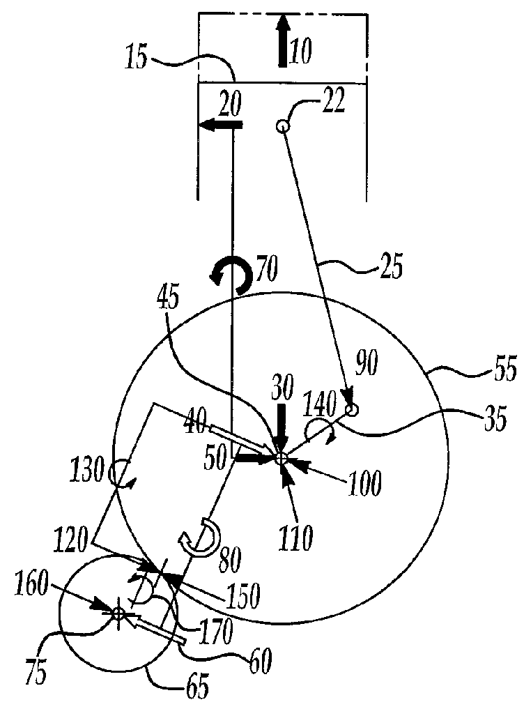
[0023]Referring now to FIG. 1, a free-body diagram is shown illustrating operation of the present invention with a counter-rotating inertia, as may be provided by an integral starter / generator (ISG), for example, to cancel moments on a flywheel associated with angular acceleration of the inertia to reduce or eliminate reaction torque on stationary powertrain structure....


PUM


Abstract

A system and method for managing inertial torque reaction of a powertrain include a selectively engageable counter-rotating component to reduce or eliminate torque reaction on stationary powertrain structure. Selectively engageable counter-rotating inertia may be provided by a simple inertial mass or by an electrical machine functioning as an integral starter / generator (ISG) to provide vehicle launch assist, regenerative braking of the vehicle, and engine cranking. Embodiments include gear-driven, chain-driven, and belt-driven counter-rotating inertias selectively coupled for counter-rotation relative to the crankshaft by a clutch, a belt-driven pulley assembly, or chain-driven intermediate shaft assembly with a hydraulically actuated coupling pin.

Description

BACKGROUND OF THE INVENTION[0001]1. Field of the Invention[0002]The present invention relates to systems and methods for managing inertial torque reaction of rotating machines.[0003]2. Background Art[0004]A conventional powertrain has a “stationary” structure that is attached to the vehicle chassis with resilient mounts. In conventional powertrains, various engine and transmission components including the crankshaft, flywheel, and torque converter of an automatic transmission, for example, rotate in the same direction such that their rotating inertia has a compounding effect. When a compression or combustion event of the engine causes an acceleration of the rotating inertia, generally, there is an equal but opposite inertial torque reaction imposed upon the stationary structure. As such, the stationary structure is not truly stationary, but instead, vibrates in opposition to the accelerations of the rotating inertia. This vibration of the stationary structure passes vibration throug...

Claims


Application Information

Patent Timeline
Patent Type & Authority Patents(United States)
IPC IPC(8): F02B75/00
CPCB60W10/06B60W30/20B60W10/30B60W10/08
Inventor BERGER, ALVINSOLFERINO, VINCE
Owner FORD GLOBAL TECH LLC
Why Eureka
Try Eureka