Variable Displacement Engine Operation With NVH Management

a technology of variable displacement and engine, applied in hybrid vehicles, instruments, analogue processes for specific applications, etc., can solve the problems of limiting the power production of the engine, increasing the pumping loss, and reducing fuel efficiency, so as to reduce or eliminate the torque reaction, no backlash, and minimal elasticity

Inactive Publication Date: 2008-06-26
FORD GLOBAL TECH LLC
View PDF30 Cites 121 Cited by
  • Summary
  • Abstract
  • Description
  • Claims
  • Application Information

AI Technical Summary

Benefits of technology

[0009]The present disclosure includes a system and method for controlling an internal combustion engine in one or more reduced displacement modes by managing NVH associated with inertial torque reaction in response to varying cylinder firing frequency and peak torque disturbances by rotating closely coupled inertial powertrain or drivetrain components in a direction opposite to the rotation of engine / motor inertial components, to reduce or eliminate torque reaction on stationary powertrain components.
[0010]In one embodiment, the present disclosure includes controlling a multi-cylinder internal combustion engine to operate in at least one reduced displacement mode by deactivating at least one cylinder and having a close-coupling device with no backlash and minimal elasticity that reverses rotation of one or more transmission or transaxle components relative to the crankshaft and other rotating engine / motor components to reduce or eliminate noise, vibration, and harshness otherwise associated with the angular acceleration / deceleration associated with the cylinder firings of the operating cylinders. The device may operate in cooperation with various drive components such as gears, belts, chains and sprockets, or any similar device used to closely couple an output component of an internal combustion engine to one or more components of the powertrain. The device causes one or more powertrain inertial components to rotate in a direction opposite to that of various engine inertial components, such as a crankshaft, and closely couples the engine / motor and drivetrain so the counter-rotating inertia reduces or eliminates the noise and vibration associated with the cylinder firings of the active cylinders that would otherwise be transmitted through the chassis. The effective inertia of the backward rotating components may be substantially matched to that of the forward rotating components using a device with an appropriate input / output ratio to create a speed differential between the backward rotating engine / motor components and the forward rotating powertrain components, or by adjusting the mass or component geometry of engine or powertrain components, for example.
[0011]In a transversely mounted internal combustion engine and transaxle, as generally used in, but not limited to, front wheel drive (FWD) vehicles, for example, the crankshaft and the torque converter may be connected using toothed wheels with a biasing element interposed therebetween to provide a stiff, non-compliant coupling without excessive lash enabling the torque converter and crankshaft to rotate in opposite directions. The biasing element may be a separate or integrated device that accommodates low-frequency component changes, such as thermal expansion or wear, while being essentially stiff or rigid to higher frequency accelerations / decelerations associated with oscillation of the crankshaft in response to cylinder firings during the reduced displacement mode. In one embodiment, the biasing element is implemented by a scissors gear with a spring preload selected to provide the desired negative torque carrying cpacity. The opposing direction of rotation of the crankshaft and torque converter reduces or eliminates the inertial torque reaction on the stationary powertrain structure to reduce or eliminate unwanted vibration and noise. This facilitates operation in reduced displacement mode at idle and low engine speeds and engine lugging, for example.
[0012]A longitudinally mounted engine and transmission application, as generally used in, but not limited to, rear wheel drive (RWD) vehicles, for example, may incorporate a simple planetary gear set to connect the crankshaft to the torque converter. Such a planetary gear set typically includes a sun gear, a ring gear, and a carrier with a plurality of pinions that are constantly in mesh with the sun and ring gears. In such an arrangement, for example, the carrier may be rendered stationary by using a plurality of fasteners to connect it with the engine / motor block. The sun gear of the planetary gear set may be connected to the crankshaft using any of a variety of methods including using conventional fasteners or alternatively splines with at least one retaining ring. Likewise, the ring gear or the annulus of the planetary gear set may be connected to the engine / motor flex plate using a plurality of fasteners. Such an arrangement allows the ring gear to rotate in a direction opposite to that of the sun gear when the carrier is non-rotating. Thus, at least one drivetrain component, such as the torque converter, will rotate in a direction opposite to that of the crankshaft and create corresponding rotational inertia to reduce or eliminate the inertial torque reaction otherwise associated with angular acceleration / deceleration of rotating components of the engine during a reduced displacement operating mode.
[0013]The present disclosure provides a number of advantages. For example, the present disclosure expands the acceptable operating range of a reduced displacement mode by effectively managing NVH otherwise associated with uneven firing intervals or operation at low speed, idle, and or lugging conditions to improve overall fuel efficiency. By reducing or eliminating NVH issues associated with reduced displacement operating modes, power output may be varied by activating / deactivating individual cylinders with reduced throttling to smooth engine power output and reduce step changes in torque. For hybrid generator / motor applications driven by the engine, torque transitions can be smoothed by adding or removing torque using the generator / motor so that no throttling is required. The present disclosure reverses rotation of conventional powertrain components using a coupling device that will accommodate thermal expansion and wear while providing an otherwise stiff or non-compliant coupling to obviate the need for additional components or mass to generate balancing inertia. This reduces any adverse impact on powertrain weight, responsiveness, and overall performance relative to conventional solutions that add components solely for balancing or canceling torque reactions associated with rotating inertia.

Problems solved by technology

As such, it is necessary to limit the engine's power production to deliver the power expected by the driver.
While airflow control is an effective way to control power output, it generally results in reduced fuel efficiency associated with increased pumping losses to move air into the cylinders, combustion heat losses, and reduced cylinder pressures.
However, operation in one or more reduced displacement modes alters the frequency and magnitude of the torque pulsations or disturbances generated by the cylinder firings, which may be transmitted through the chassis and result in undesirable noise and vibration within the vehicle cabin.
As such, operation in the reduced displacement mode is typically limited or constrained to mid-range engine speeds at low or moderate loads.
Unfortunately, the constraints that have the most negative impact on the potential fuel economy benefit are associated with unacceptable NVH, including operating at low RPM, idle, and engine lugging, for example.
Other NVH constraints also adversely impacted the available fuel economy benefit by preventing reduced displacement operation at idle (−2.1%), near idle (such as below 1000 rpm) (−1.4%), in first and second gear (−2.0%), and during engine warm-up (−0.9%).
Prior art approaches to managing NVH in variable displacement engines include limiting variable displacement operation, which negatively impacts the potential fuel economy benefit as previously described, tuning the powertrain mounts or using actively controlled mounts to minimize transmission of vibrations, and active noise cancellation within the vehicle cabin.
Also, there was no expressed intent to match the effective magnitudes of the forward and backward rotating inertias.
U.S. Pat. No. 5,282,444 to Ito discloses a powerplant for a personal watercraft that uses a counter-rotating member to improve vehicle stability, but does not address NVH issues, does not eliminate backlash in the gear set, and does not operate in a reduced displacement mode.
While acceptable for some applications, none of the prior art approaches passively manages NVH associated with the engine firing frequency to expand available operating conditions for a reduced displacement mode using existing powertrain components.

Method used


Image

  • Variable Displacement Engine Operation With NVH Management
  • Variable Displacement Engine Operation With NVH Management
  • Variable Displacement Engine Operation With NVH Management

Examples


Embodiment Construction

)

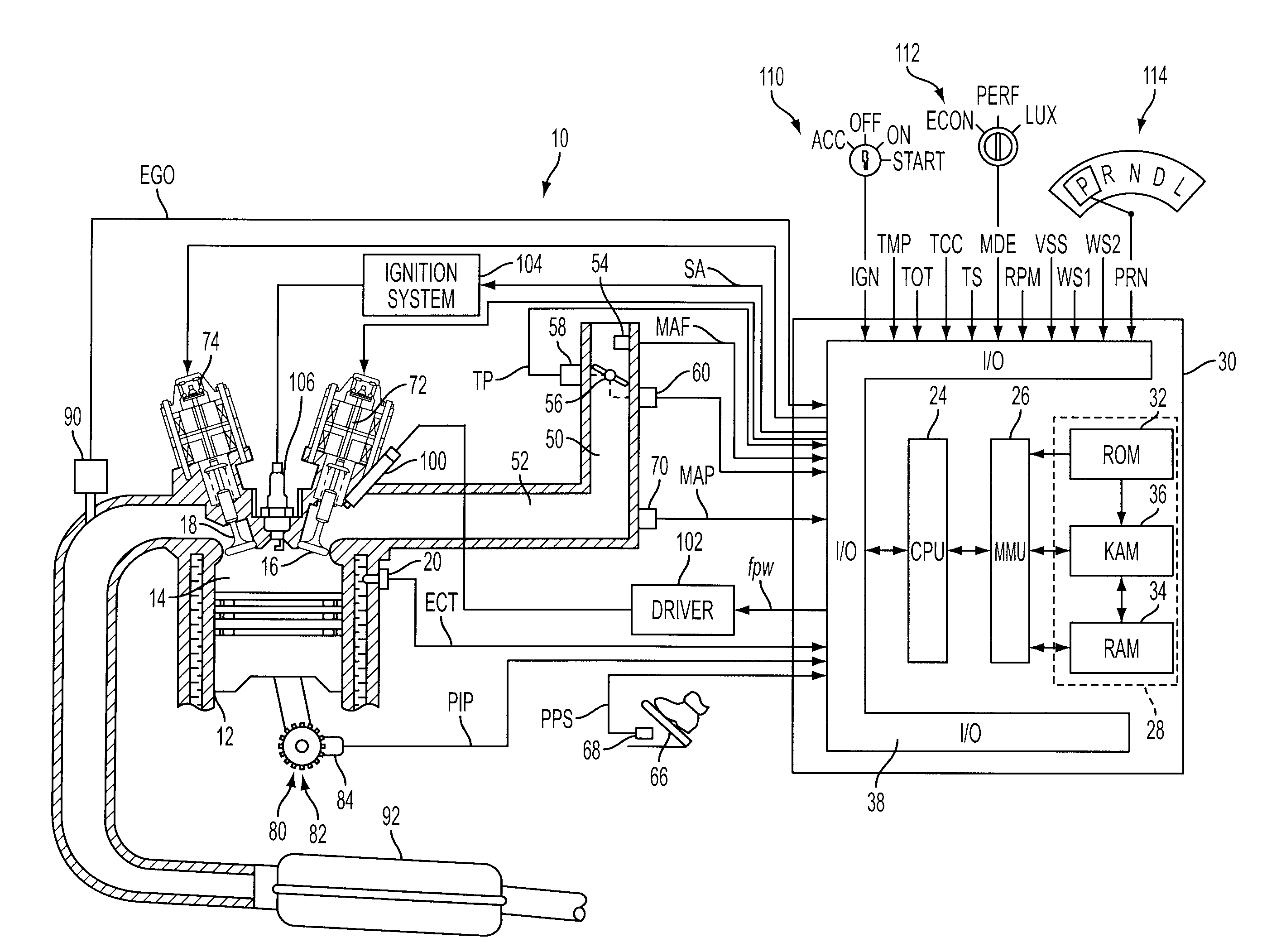
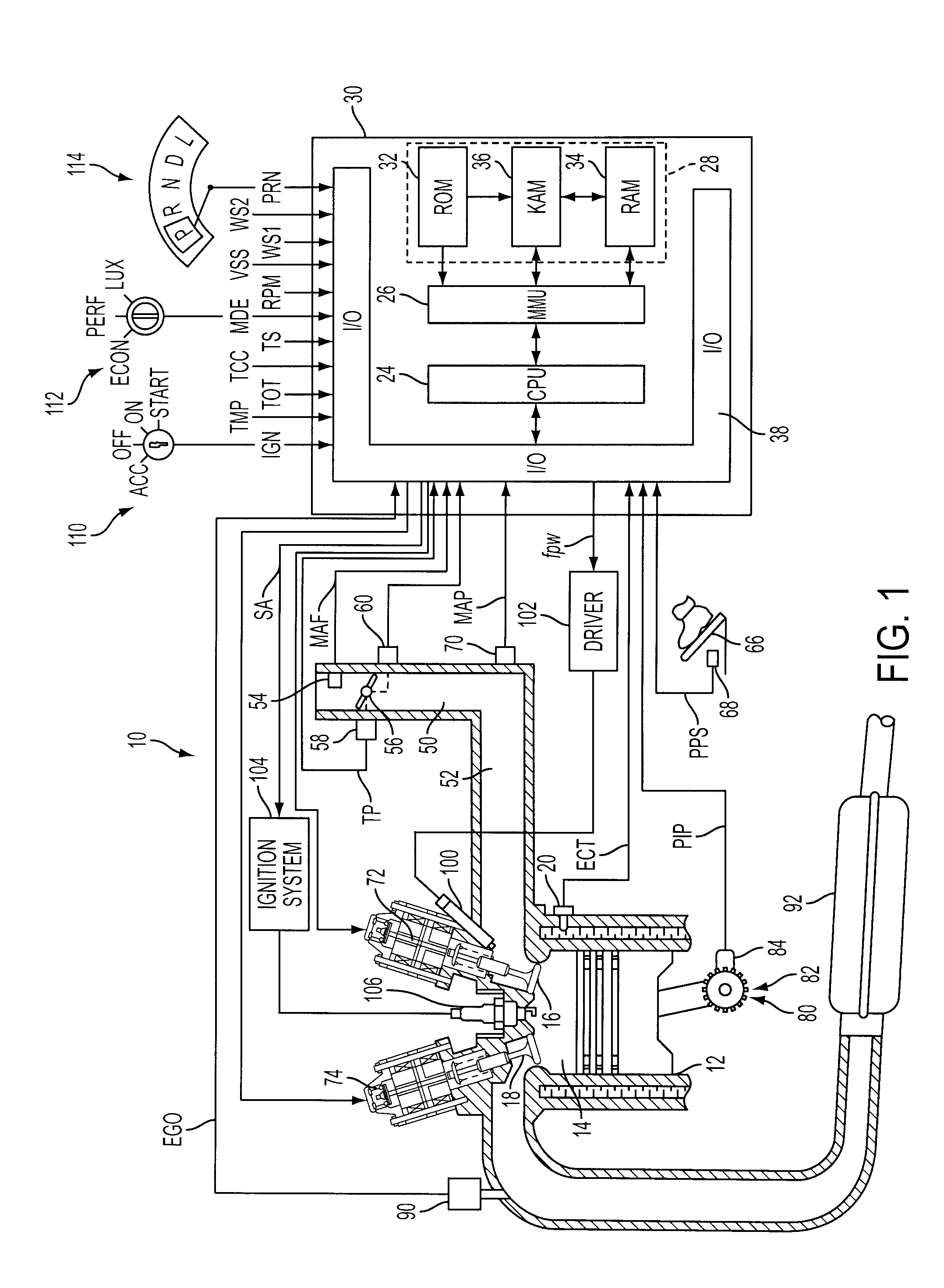
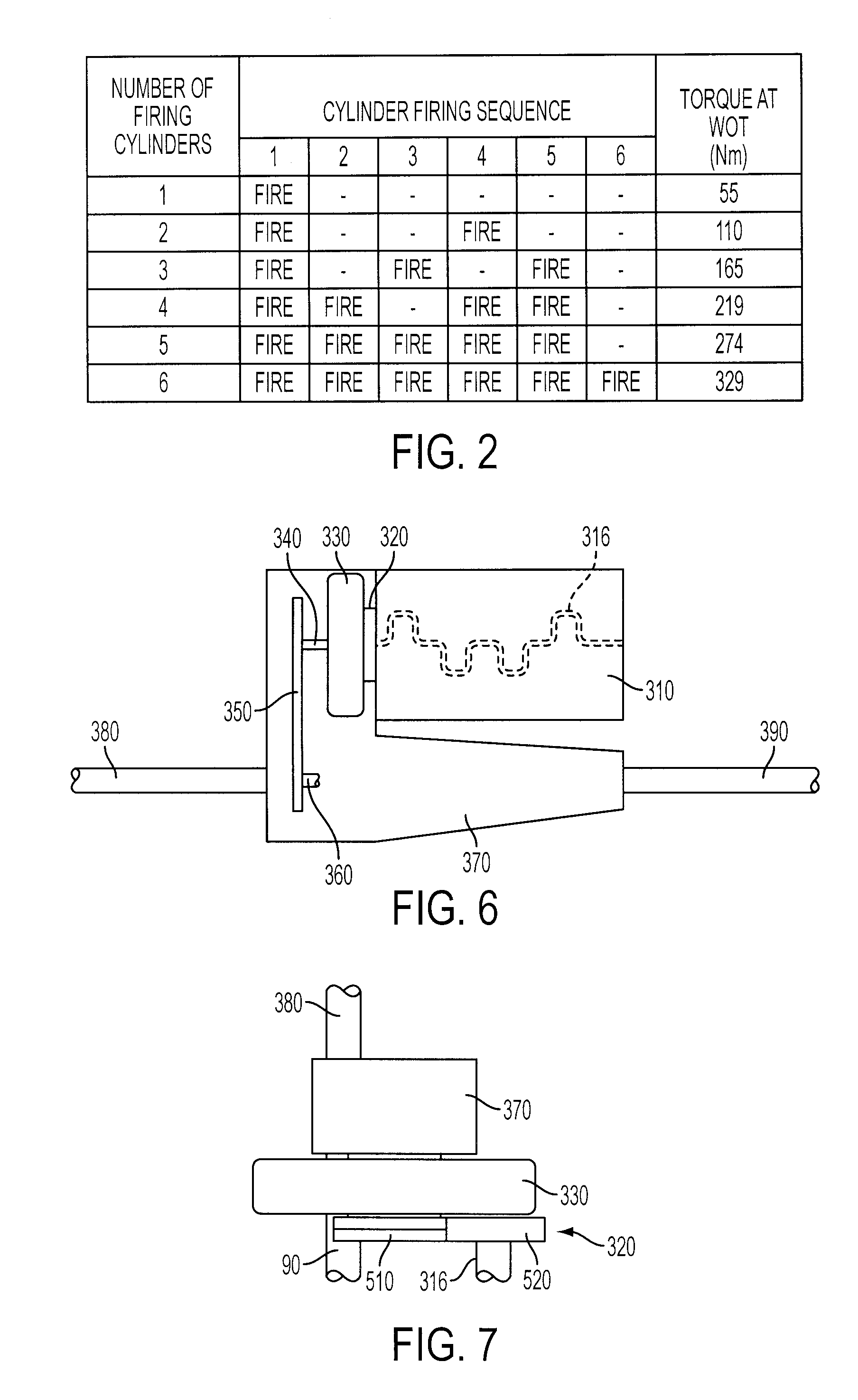
[0027]As those of ordinary skill in the art will understand, various features of the present disclosure as illustrated and described with reference to any one of the Figures may be combined with features illustrated in one or more other Figures to produce embodiments of the present disclosure that are not explicitly illustrated or described. The combinations of features illustrated provide representative embodiments for typical applications. However, various combinations and modifications of the features consistent with the teachings of the present disclosure may be desired for particular applications or implementations. The present disclosure relates to a system and method for controlling a reduced displacement mode or modes of a multiple cylinder internal combustion engine while managing NVH associated with torsional accelerations / decelerations associated with cylinder firings so that the reduced displacement mode can be used under more diverse operating conditions without being ...


PUM


Abstract

A system and method for controlling an internal combustion engine operable with a first cylinder firing frequency and a second cylinder firing frequency to reduce or eliminate transmission of torsional vibrations associated with the second cylinder firing frequency to reduce or eliminate constraints on reduced displacement mode operation using a closely coupled drive train component rotating in an opposite direction relative to rotating components of the engine. A close coupling device allows the inertia of the counter-rotating elements to reduce or eliminate the torque reaction of the drivetrain associated with acceleration and deceleration of the engine crankshaft in response to the second cylinder firing frequency in the reduced displacement mode.

Description

CROSS-REFERENCE TO RELATED APPLICATION[0001]This application is a continuation-in-part of, and claims priority to commonly owned and copending U.S. patent application Ser. No. 10 / 907,721 filed on Apr. 13, 2005, the disclosure of which is hereby incorporated by reference in its entirety.BACKGROUND[0002]1. Technical Field[0003]The present disclosure relates to systems and methods for controlling an internal combustion engine to operate in a reduced or variable displacement mode while managing noise, vibration, and harshness (NVH).[0004]2. Background Art[0005]Internal combustion engines are generally most fuel efficient when operating unthrottled at a compression ratio that allows the ignition timing to produce best torque without detonation. To meet customer expectations for acceleration and responsiveness, engines are often sized such that the maximum power exceeds the vehicle's power requirements under most operating conditions. As such, it is necessary to limit the engine's power p...

Claims


Application Information

Patent Timeline
Patent Type & Authority Applications(United States)
IPC IPC(8): G06F17/00F16H57/00
CPCB60K6/365B60K6/48B60W10/02B60W10/08Y10T477/631B60W30/20F16H57/0006Y02T10/6221B60W20/00Y02T10/62B60W20/15
Inventor BERGER, AL HENRYSOLFERINO, VINCE PAUL
Owner FORD GLOBAL TECH LLC
Why Eureka
Try Eureka