Strainer, and snappy holding structure by the strainer
a holding structure and strainer technology, applied in the field of strainers, can solve the problems of small movement allowance of the switch lever in the up (contact) state, unstable positional attitude of the cam mechanism in contact/noncontact state, and prone to backlash of the cam mechanism, etc., to achieve no backlash, easy operation with small force, and simple structure
- Summary
- Abstract
- Description
- Claims
- Application Information
AI Technical Summary
Benefits of technology
Problems solved by technology
Method used
Image
Examples
first embodiment
First, referring to FIGS. 1 to 9, a description will be given of the
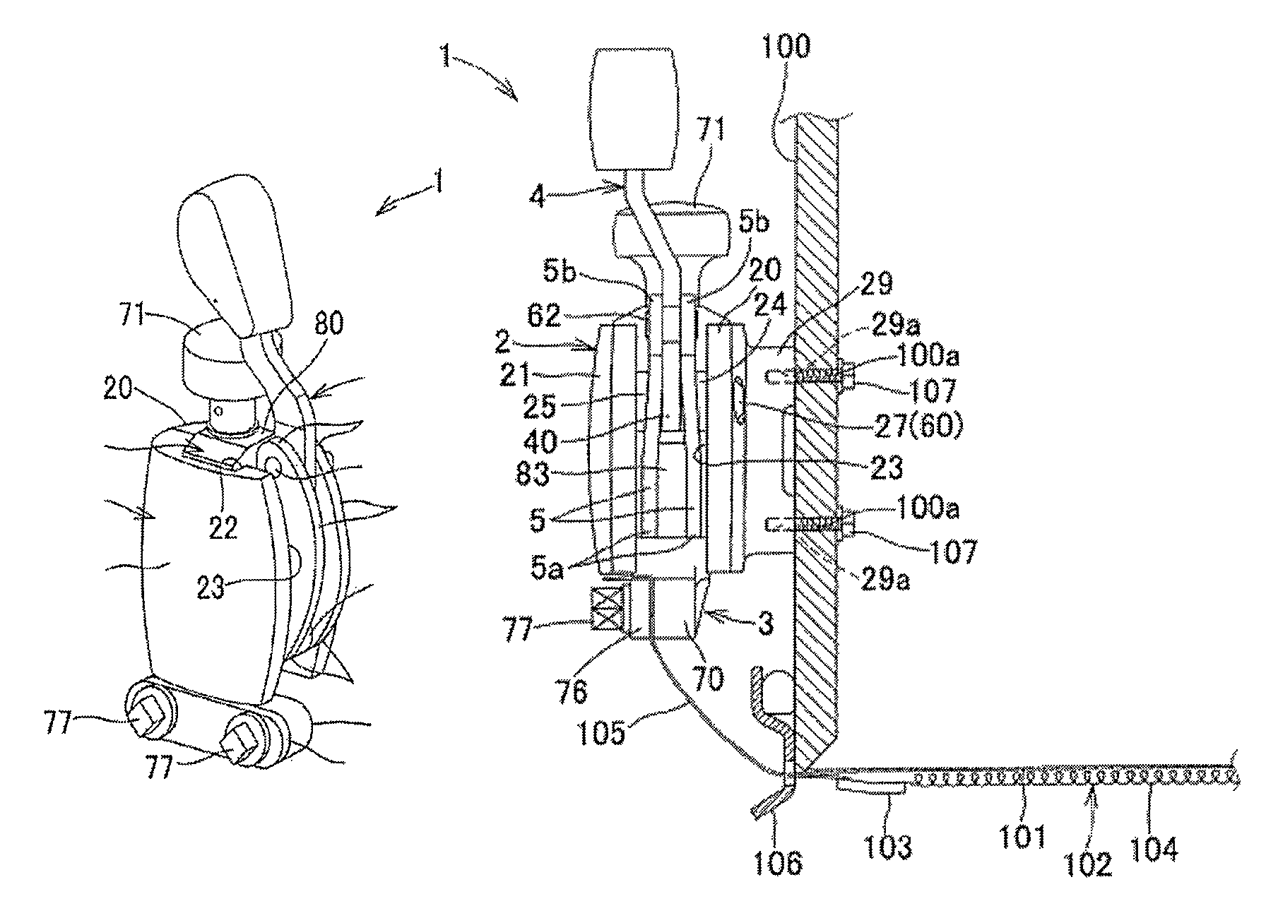
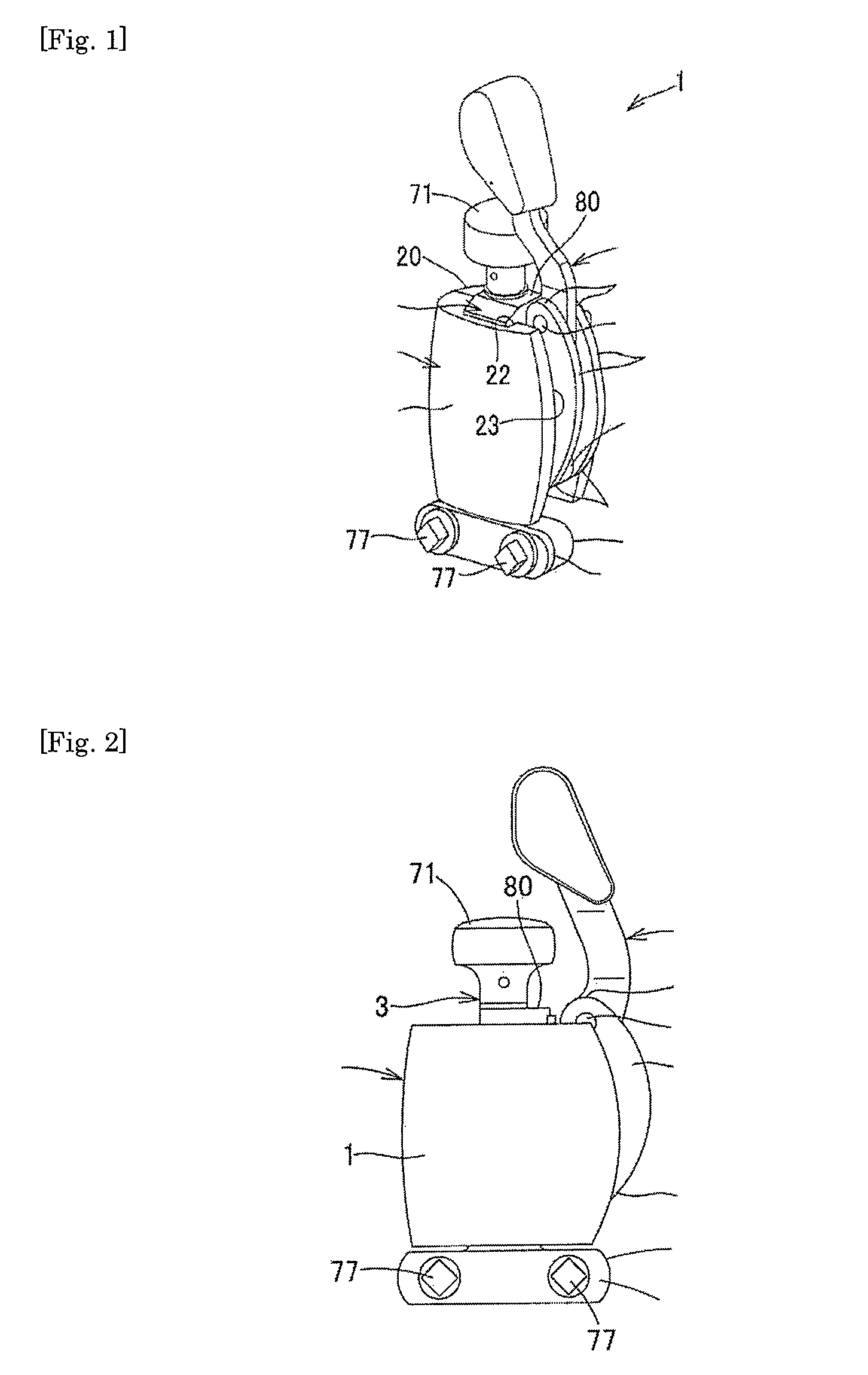
As shown in FIGS. 1 to 3, a strainer 1 includes a base element 2 that is fixed on a shell body 100 side of a drum; a snare assembly holding element 3 that is engaged with the base element 2 to freely slide up and down, and that has its bottom end side connected to a snare assembly 102; and an operating lever 4 that slides up and down the snare assembly holding element 3 relative to the base element 2, so as to switch the snare assembly 102 between contact / noncontact states relative to a drumhead 101.
As can also be seen from FIGS. 5 and 9, the present invention is characterized in further including a link 5 that pivotally and rotatably support a pedestal end of the operating lever 4 on the base element 2 via a shaft portion 60, the link 5 having its one end 5a rotatably connected to a site located lower than the shaft portion 60 of the operating lever 4 in the snare assembly holding element 3, and having its other en...
second embodiment
Next, referring to FIGS. 10 to 16, a description will be given of the
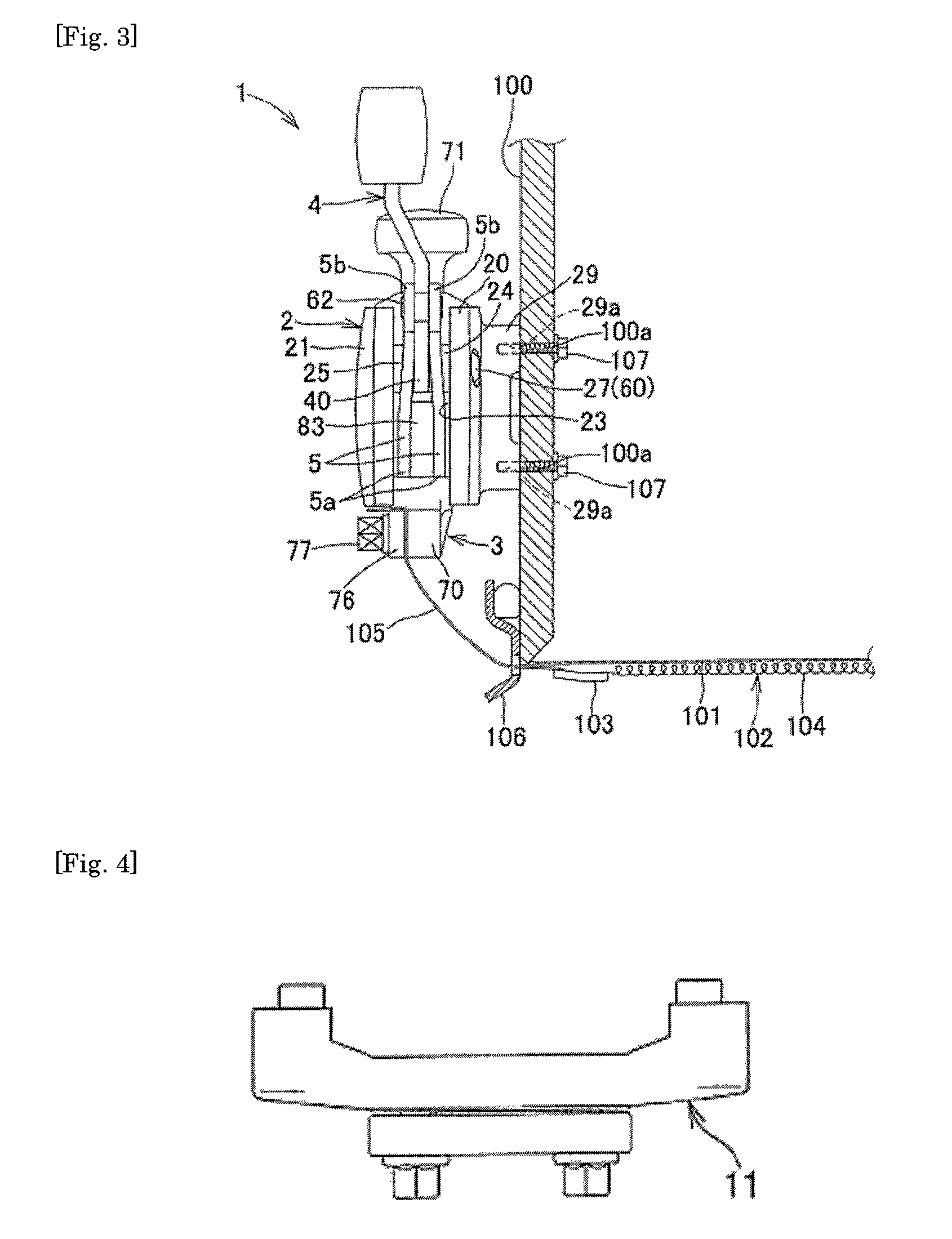
In connection with the second embodiment, the description will mainly be given of a snare assembly holding structure according to the present invention. FIG. 10 is a partial cross-sectional view showing a snare drum in which a snare assembly is held by a pair of strainers 1 and 11. In the drawing, the reference numeral 1 denotes a strainer equipped with a switch mechanism; 11 denotes a fixed type strainer; 100 denotes a drum shell body; 102 denotes a snare assembly; 105 denotes a snare assembly string at the snare assembly end; and St denotes a snare assembly holding structure. In the present embodiment, while the one strainer 1 is equipped with a switch mechanism and the other strainer 11 is of a fixed type, as in the conventional ones, both of the strainers may each be equipped with a switch mechanism. Further, in connection with the present embodiment, while the description will be given of an exemplary case whe...
third embodiment
Next, referring to FIGS. 18 to 22, a description will be given of the
The present embodiment is another embodiment of the strainer 1 equipped with a switch mechanism, wherein, as shown in FIG. 18, an elastic member 92 is protrusively formed toward the snare assembly holding element 3 inside the guide groove 22 that slidably guides the snare assembly holding element 3, and a vertically elongated concave groove 85 that receives the elastic member 92 so as to be relatively movable up and down is provided at a side surface of the snare assembly holding element 3 facing the guide groove 22. More specifically, as shown in FIGS. 20 and 21, a fit hole 90 into which the elastic member 92 is partially protrusively fit is formed at the bottom surface of the guide groove 22 on the split housing 20 side, and by a screw 93 that screws with a screw hole 91 formed at the fit hole 90, the elastic member 92 is fixed to the fit hole 90. Further, the concave groove 85 is formed at a side surface of the ...
PUM
 Abstract
Description
Claims
Application Information
 - R&D
- Intellectual Property
- Life Sciences
- Materials
- Tech Scout
- Unparalleled Data Quality
- Higher Quality Content
- 60% Fewer Hallucinations
Browse by: Latest US Patents, China's latest patents, Technical Efficacy Thesaurus, Application Domain, Technology Topic, Popular Technical Reports.
© 2025 PatSnap. All rights reserved.Legal|Privacy policy|Modern Slavery Act Transparency Statement|Sitemap|About US| Contact US: help@patsnap.com


