Cleaning sheet

a cleaning sheet and fiber technology, applied in the field of cleaning sheets, can solve the problems of insufficient cleaning of carpets, insufficient cleaning of dirt or the like, limited dirt twined and taken out by fibers, etc., and achieve the effect of effectively twining and taking out dirt, increasing the cushion properties of cleaning sheets

Active Publication Date: 2012-07-24
KIKUO YAMADA
View PDF10 Cites 54 Cited by
  • Summary
  • Abstract
  • Description
  • Claims
  • Application Information

AI Technical Summary

Benefits of technology

[0007]In light of the above problem, an object of the present invention is to provide a cleaning sheet that can sufficiently wipe off even relatively large dirt particles.
[0009]In the present invention, a cleaning portion provided with fiber bound materials is provided on a base sheet to constitutes a cleaning sheet. Accordingly, fibers constituting fiber bound materials of the cleaning portion can sufficiently twine and take out relatively large dust and dirt particles (particulate matter) and effectively scratch dust and dirt so as to exhibit capture and maintenance performance. In addition, the cleaning sheet is provided with a fiber bound material different from a base sheet on the base sheet. Thus, it is possible to comparatively freely adjust the lengths of fibers and also tightly capture relatively large dirt particles.
[0010]The present invention can arrange and place a plurality of fiber bound materials on a base sheet and bind thereto to constitute a cleaning portion, thereby being capable of twining and taking out still more dirt particles.
[0012]In the present invention, the cleaning portion may be formed by binding plural kinds of fiber bound materials having different fiber lengths to a base sheet. This constitution makes it possible to twine and take out fine pieces of dirt with fiber bound materials having fibers of short lengths and to twine and take out relatively large dirt particles with fiber bound materials having fibers of long lengths.
[0013]According to the present invention, the cleaning portion may be formed by binding it to a base sheet in such a manner that portions of the fiber bound materials are overlapped with each other, and doing so enables a bulky cleaning portion. Thus, cushion properties of a cleaning sheet can be increased, so that the cleaning portion can be more sufficiently fitted to the cleaning face of material to be cleaned, thereby effectively twining and taking out dirt.

Problems solved by technology

However, dusters are simply used to beat dirt or the like out of matter to be cleaned and thus are insufficient to wipe dirt or the like therefrom.
Dirt twined and taken out by the fiber is limited to comparatively small sizes and it is difficult to twine and take off relatively large dirt particles by means of fiber of the brush portion.
Therefore, dirt rarely contacts the central portion of the cleaning sheet, thereby posing a problem in that it is impossible for the central portion of a cleaning sheet to also have a function of wiping dirt off to thoroughly use the entire face of the cleaning sheet.

Method used


Image

  • Cleaning sheet
  • Cleaning sheet
  • Cleaning sheet

Examples


second embodiment

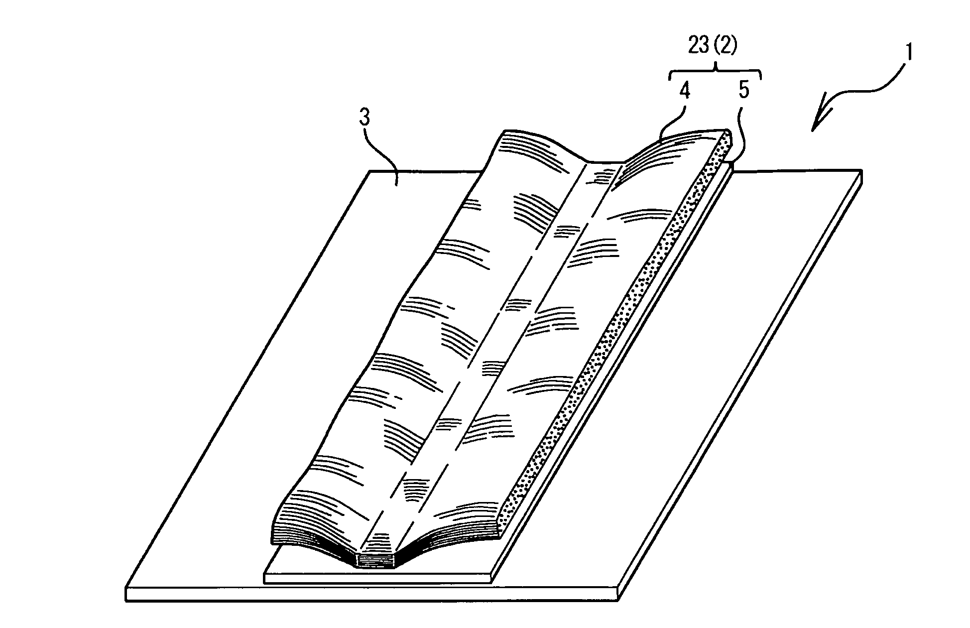
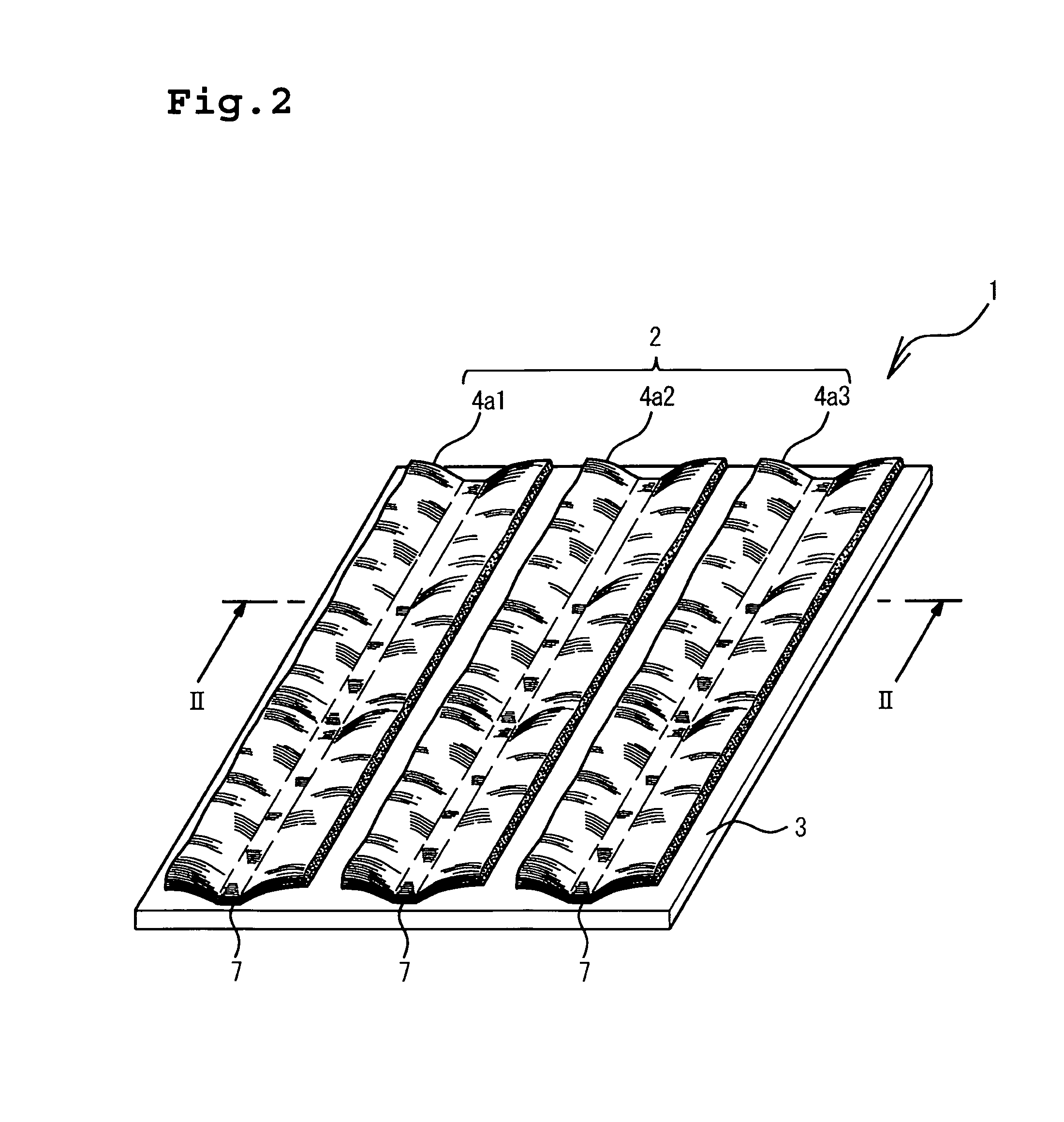
[0040]For example, in the cleaning sheet 1 of the present invention, as shown in FIGS. 2 and 4A, the fiber bound materials 4a which include fiber bound materials 4a1, 4a2, 4a3 provided a bent portion respectively, may be disposed on the same side or surface surface of the base sheet 3 in a plurality of numbers. In this case, in the cleaning sheet 1, the plurality of fiber bound materials 4a which include the fiber bound materials 4a1, 4a2, 4a3 is aligned and disposed at intervals in the flow, i.e. longitudinal direction of the fibers constituting the fiber bound materials 4.

third embodiment

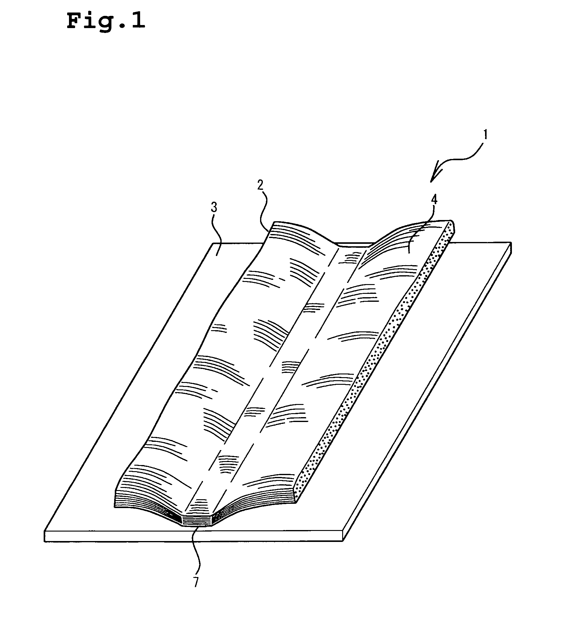
[0041]Where the plurality of fiber bound materials 4 are disposed on the base sheet 3, the fiber bound materials which are provided with the bent portions may be used for a part or all of the plurality of fiber bound materials 4. For example, with regard to the cleaning sheet 1 of a third embodiment, as shown in FIG. 3, the three fiber bound materials 4 are joined or fixed to the base sheet 3, and all of them may be the fiber bound materials 4, 4a1, 4a2, 4a3 which are respectively provided with the bent portion 6. In this case, the plurality of fiber bound materials 4 is joined to the base sheet 3 at their bent area to define bent portion 6 and also to form fixing portions 7, thereby forming the cleaning portion 2.

[0042]In the case where the fiber bound materials 4 of the base sheet 3 are disposed in a plurality of numbers, the disposition number of the fiber bound materials 4 disposed on the base sheet 3 is not particularly limited and usually two to ten materials are preferred.

[00...

fourth embodiment

[0044]Where the fiber bound materials 4 are disposed on the base sheet 3 in a plurality of numbers, the fiber bound materials 4 different in length of fibers may be disposed on the base sheet 3 of a fourth embodiment, as shown in FIGS. 4A, 4C, 4D and 5. At this time, the fiber bound materials 4 can be placed in arbitrary positions.

[0045]For example, as shown in FIG. 4B, the fiber bound materials may be placed on the base sheet 3 in such a way that fiber bound materials 4a (4a1, 4a2, 4a3) having short fiber lengths are in proximity to the central position of the base sheet 3 rather than fiber bound materials 4b (4b1, 4b2, 4b3) having long fiber lengths and each may be bound to the base sheet 3.

[0046]As shown in FIG. 4C, the fiber bound materials 4a, 4b may be alternately disposed at intervals, each binding to the base sheet 3.

[0047]In the case where the fiber bound materials 4 are placed on the base sheet 3, the fiber bound materials 4a (4a1, 4a3), 4b having fibers of different lengt...


PUM

PropertyMeasurementUnit
thicknessaaaaaaaaaa
diametersaaaaaaaaaa
diametersaaaaaaaaaa

Abstract

Provided is a cleaning sheet in which a plurality of fiber bound materials produced by bundling a lot of fibers is joined on a base sheet, and at least adjacent two bound fiber materials have respectively different length in the longitudinal direction of the fibers, to constitute a cleaning portion and which can sufficiently wipe off even relatively large dirt particles.

Description

BACKGROUND OF THE INVENTION[0001]1. Field of the Invention[0002]The present invention relates to a cleaning sheet.[0003]2. Description of the Related Art[0004]Dusters are conventionally known as cleaning tools to remove dust or dirt stuck to furniture such as wardrobes, electric appliances such as personal computers and lights, walls inside buildings, thresholds, head jamb (kamoi), and the like. However, dusters are simply used to beat dirt or the like out of matter to be cleaned and thus are insufficient to wipe dirt or the like therefrom.[0005]Japanese Patent Application Laid-Open (JP-A) No. 2000-245670 is referred, which proposes that a long fiber filament is intermittently jointed onto the surface of a substrate sheet in its fiber flow direction, the long fiber filament is cut at its joint portions, and many different brushes are formed on at least one surface of the substrate sheet to produce a cleaning sheet, so that dirt or the like is wiped from matter to be cleaned by use o...

Claims


Application Information

Patent Timeline
Patent Type & Authority Patents(United States)
IPC IPC(8): A47L13/12A47L13/20
CPCA47L13/12A47L13/38A47L13/44A47L25/005B32B5/022B32B5/024B32B5/12B32B7/045B32B7/12B32B27/12B32B29/02A47L13/255Y10T428/24752B32B2250/20B32B2262/0246B32B2262/0253B32B2262/0261B32B2262/0284B32B2262/062B32B2262/08B32B2432/00B32B7/05Y10T428/249921
Inventor YAMADA
Owner KIKUO YAMADA
Why Eureka
Try Eureka