Input protection circuit

a protection circuit and input technology, applied in the field of input protection circuits, can solve the problems of insufficient current, overvoltage condition yet low amount of available current, unwanted voltage in the secondary coil of the secondary circuit, etc., and achieve the effect of dissipating a sufficient amount of hea

Active Publication Date: 2012-09-04
PHILIPS IP VENTURES BV
View PDF10 Cites 45 Cited by
  • Summary
  • Abstract
  • Description
  • Claims
  • Application Information

AI Technical Summary

Benefits of technology

[0007]The present invention provides a protection circuit that includes a voltage clamp thermally coupled to a thermal cutoff. The voltage clamp provides some protection from overvoltage conditions. If an overvoltage condition persists for too long the voltage clamp dissipates a sufficient amount of heat to activate the thermal cutoff creating an open circuit that protects the rest of the circuit.
[0010]In another embodiment, the protection circuit of the present invention is used in combination with other protection circuitry to provide a wider scope of protection. In one embodiment, a combination of protection circuitry defines a window of operation for the circuit, different protection circuitry triggers on different fault conditions, both expected and unexpected. For example, some protection circuitry may be designed to protect the load, while other protection circuitry may be designed to protect the secondary circuit as a whole. Some protection circuitry may be designed to protect against overvoltage conditions and other circuitry may be designed to protect against overcurrent conditions. Further, some protection circuitry may be designed to protect against transients or persistent fault conditions. In one embodiment, three distinct tiers of protection are provided: 1) an electrical fuse provides increased protection for the circuit generally against large transients; 2) a field effect transistor controlled by a microprocessor provides load protection in response to one or more sensed characteristics, including frequency, temperature, input voltage or input current; and 3) a voltage clamp protection circuit including a thermal cutoff provides increased general circuit protection against both transient and persistent overvoltage conditions, even where current is low.

Problems solved by technology

In this embodiment, third party magnetic fields may induce unwanted voltage in the secondary coil of the secondary circuit.
In some circumstances, such as an inductively powered remote device, there may be an overvoltage condition yet a low amount of available current.
However, a typical voltage clamp cannot sustain exposure to an overvoltage condition indefinitely.
Eventually, the heat generated by the voltage clamp can cause the voltage clamp to malfunction.

Method used


Image

  • Input protection circuit
  • Input protection circuit
  • Input protection circuit

Examples


Embodiment Construction

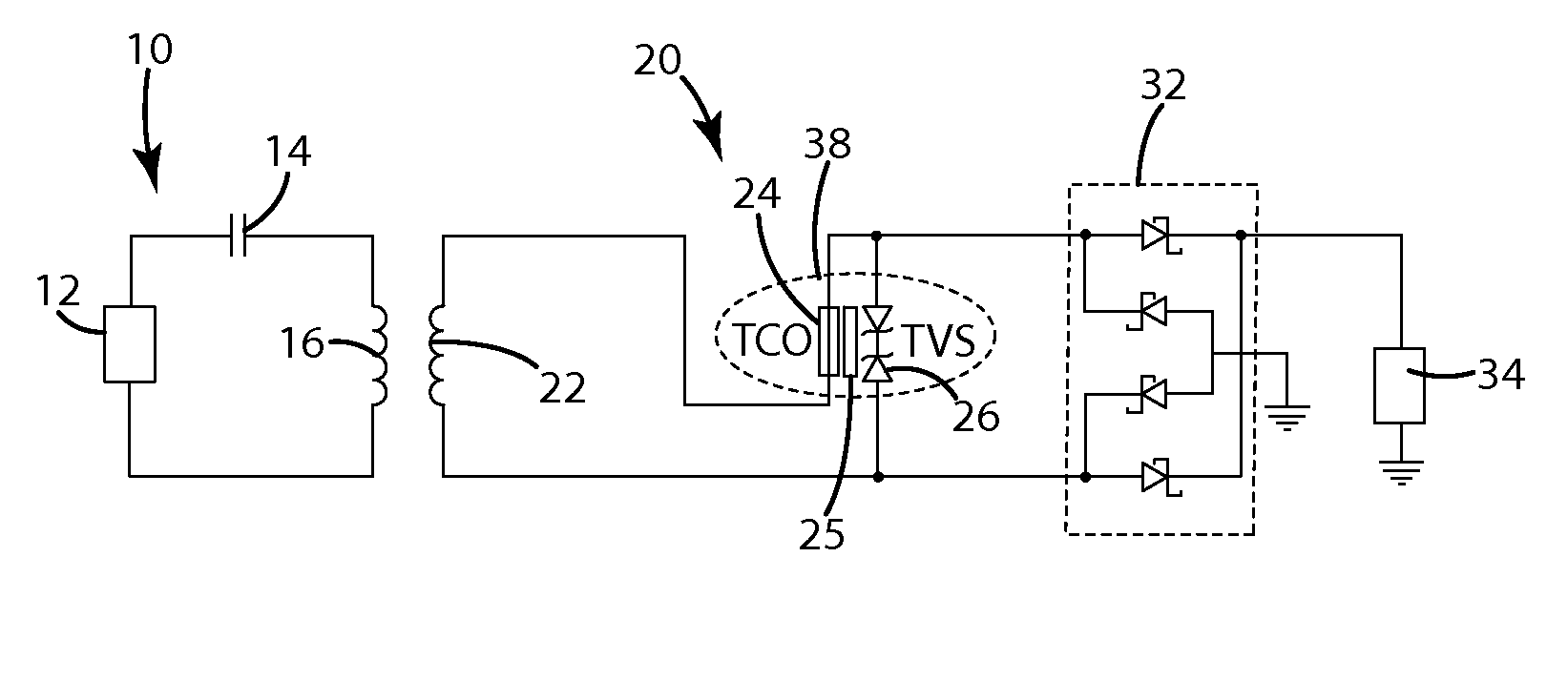
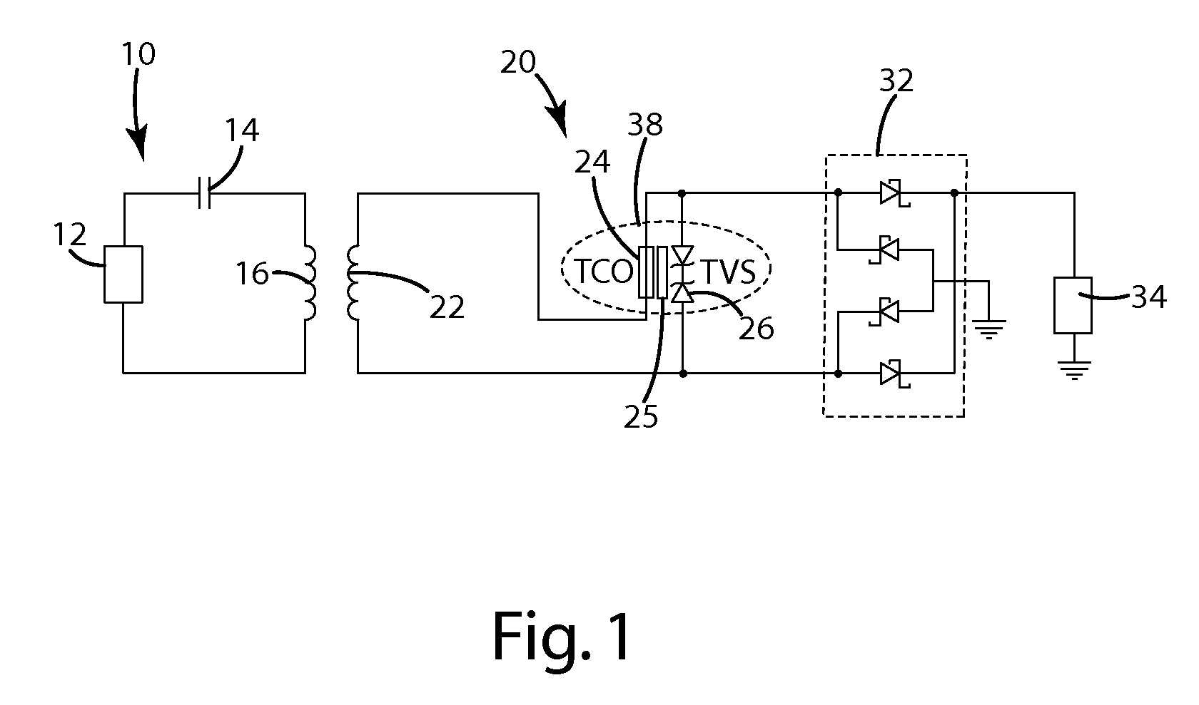
[0016]Referring now to FIG. 1, a diagram of an inductively coupled system having a voltage clamp protection circuit 38 in accordance with an embodiment of the present invention is shown. The illustrated inductively coupled system includes an inductive power supply 10 and a remote device 20. The inductive power supply 10 includes a power supply circuit 12, a capacitor 14 and a primary coil 16. The remote device 20 includes a secondary coil 22, a thermal cutoff 24, a voltage clamp 26, optional thermal adhesive 25, an optional rectification circuit 32 and a load 34. The voltage clamp protection circuit 38 generally includes at least two components, the voltage clamp 26 and the thermal cutoff 24. In the illustrated embodiment, the voltage clamp 26 and the thermal cutoff 24 are thermally coupled to each other with an optional thermal adhesive 25. The thermal cutoff 24 is electrically connected between the secondary coil 22 and the rest of the circuit. The voltage clamp 26 clamps the inpu...


PUM


Abstract

A voltage clamp protection circuit to protect against overvoltage conditions where there is insufficient current to blow a fuse. The voltage clamp protection circuit includes a voltage clamp and a thermal cutoff. The voltage clamp clamps any overvoltage to a clamping voltage. If an overvoltage condition persists for too long the voltage clamp dissipates a sufficient amount of heat to activate the thermal cutoff creating an open circuit that protects the rest of the circuit. The voltage clamp protection circuit may be used in combination with a variety of other protection circuits to provide increased protection.

Description

[0001]This application claims the benefit of U.S. Provisional Patent Application 61 / 048,036, which was filed on Apr. 25, 2008.BACKGROUND OF THE INVENTION[0002]The present invention relates to an input protection circuit suitable for use in an inductively coupled circuit or essentially any other type of electrical circuit.[0003]There are many advantages to inductive coupling. One advantage is that inductive coupling allows additional opportunities for simple and efficient interoperability where devices can be used interchangeably. However, circuit designs that “cut the cord” and enable this interchangeability have the potential to make the circuit vulnerable to third party systems. That is, magnetic fields produced by third party systems may inadvertently energize the secondary coil in a remote device and provide an inappropriate amount of power. In some circumstances the power from these third party sources can be destructive. As wireless power becomes more widespread so too will th...

Claims


Application Information

Patent Timeline
Patent Type & Authority Patents(United States)
IPC IPC(8): H02H5/04H02J7/00
CPCH02H9/042
Inventor MOLLEMA, SCOTT A.BAARMAN, DAVID W.ZEIK, ANDREW C.LIFF, DALE R.BLAHA, MARK A.
Owner PHILIPS IP VENTURES BV
Why Eureka
Try Eureka