Eddy current heat generating apparatus

a heat generating apparatus and eddy current technology, applied in the direction of electric/magnetic/electromagnetic heating, asynchronous induction clutches/brakes, greenhouse gas reduction, etc., can solve the problems of carbon dioxide generation accompanying burning fossil fuels, and achieve the effect of sufficient heat generation, high magnetic flux density and thermal energy recovery

Active Publication Date: 2020-05-26
NIPPON STEEL CORP
View PDF29 Cites 0 Cited by
  • Summary
  • Abstract
  • Description
  • Claims
  • Application Information

AI Technical Summary

Benefits of technology

[0018]In the eddy current heat generating apparatus according to the present invention, the magnetic pole arrangements of adjacent ones of the magnets arrayed to face the heat generator are opposite to each other. Accordingly, the magnetic fields of the magnets spread out, and the magnetic flux density reaching the heat generator becomes high. Accordingly, the eddy currents generated in the heat generator by the effects of magnetic fields from the magnets become high, thereby allowing for a sufficient amount of heat generation. Thus, according to the present invention, thermal energy can be recovered from the kinetic energy of the rotary shaft efficiently.

Problems solved by technology

In recent years, generation of carbon dioxide accompanying burning of fossil fuels is acknowledged as a problem.

Method used


Image

  • Eddy current heat generating apparatus
  • Eddy current heat generating apparatus
  • Eddy current heat generating apparatus

Examples


first embodiment

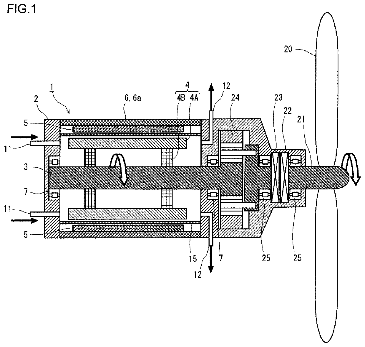
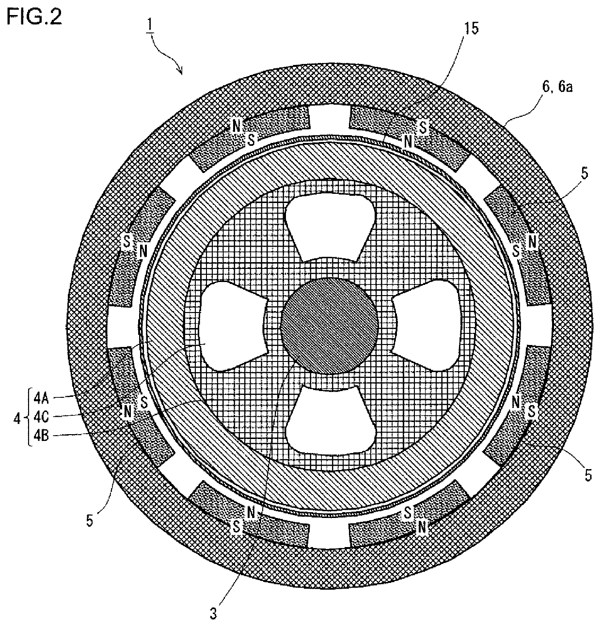
[0046]FIG. 1 is a longitudinal sectional view of a heat generating apparatus according to a first embodiment. FIG. 2 is a cross-sectional view of the heat generating apparatus according to the first embodiment. The heat generating apparatus illustrated in FIGS. 1 and 2 is mounted in a wind electric generating facility. The heat generating apparatus 1 according to the first embodiment includes a rotary shaft 3, a heat generator 4, a plurality of permanent magnets 5, and a magnet holder 6. The rotary shaft 3 is rotatably supported by a fixed non-rotative body 2 via a bearing 7.

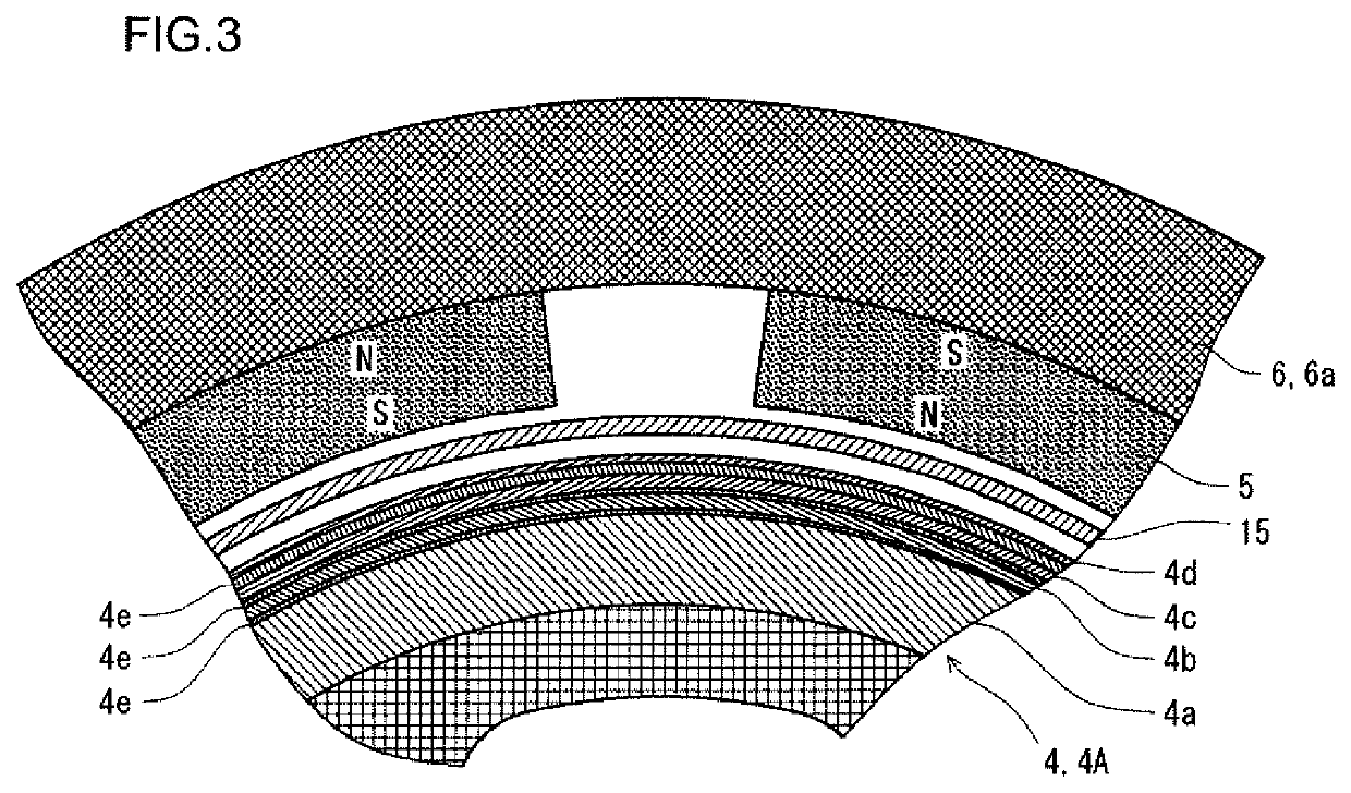
[0047]The heat generator 4 is fixed to the rotary shaft 3. The heat generator 4 includes a cylindrical member 4A that is coaxial with the rotary shaft 3, and a disk-shaped connection member 4B connecting the cylindrical member 4A and the rotary shaft 3. A plurality of through holes 4C are made in the connection member 4B for weight saving and cooling. The magnet holder 6 is disposed in the outer side of the heat...

second embodiment

[0066]FIG. 4 is a cross-sectional view of a heat generating apparatus according to a second embodiment. The heat generating apparatus 1 according to the second embodiment is based on the structure of the heat generating apparatus 1 according to the first embodiment. The same applies to the third and fourth embodiments which will be described later. The heat generating apparatus 1 according to the second embodiment differs from the heat generating apparatus 1 according to the first embodiment principally in the way of arranging the magnets 5.

[0067]As shown in FIG. 4, the magnets 5 are circumferentially arrayed on the inner peripheral surface of the cylindrical member 6a across the whole circumference. The magnetic poles (north pole and south pole) of each of the magnets 5 are circumferentially arranged, and the magnetic pole arrangements of circumferentially adjacent ones of the magnets 5 are opposite to each other. In the second embodiment, the cylindrical member 6a directly holding...

third embodiment

[0070]FIG. 5 is a longitudinal sectional view of a heat generating apparatus according to a third embodiment. The heat generating apparatus 1 according to the third embodiment differs from the heat generating apparatus 1 according to the first embodiment principally in the way of arranging the magnets 5.

[0071]As shown in FIG. 5, the magnets 5 are axially arrayed on the inner peripheral surface of the cylindrical member 6a across the whole axial length. The magnets 5 are cylindrical. The magnetic poles (north pole and south pole) of each of the magnets 5 are axially arranged such that the magnetic pole arrangements of axially adjacent ones of the magnets 5 are opposite to each other. In the third embodiment, the cylindrical member 6a directly holding the magnets 5 is made of a non-magnetic material as with the second embodiment. Pole pieces 9 made of a ferromagnetic material are provided between the axially arrayed magnets 5. Further, pole pieces 9 are provided at both ends of the ax...


PUM


Abstract

The disclosed heat generating apparatus includes: a rotary shaft, a heat generator, a plurality of permanent magnets, a magnet holder, and a heat recovery system. The rotary shaft is rotatably supported by a non-rotative body. The heat generator is fixed to the rotary shaft. The magnets are arrayed to face the heat generator with a gap such that magnetic pole arrangements of adjacent ones of the magnets are opposite to each other. The magnet holder holds the magnets and is fixed to the body. The heat recovery system collects heat generated in the heat generator.

Description

TECHNICAL FIELD[0001]The present invention relates to a heat generating apparatus that recovers thermal energy from kinetic energy of a rotary shaft, and more particularly to an eddy current heat generating apparatus employing permanent magnets (hereinafter referred to simply as “magnets”) and utilizing eddy currents generated by the effects of magnetic fields from the magnets.BACKGROUND ART[0002]In recent years, generation of carbon dioxide accompanying burning of fossil fuels is acknowledged as a problem. Therefore, utilization of natural energy, such as solar thermal energy, wind energy, hydro-energy and the like, is promoted. Among the natural energy, wind energy and hydro-energy are kinetic energy of a fluid. Conventionally, electric power has been generated from kinetic energy of a fluid.[0003]For example, in a typical wind electric generating facility, a propeller receives wind and thereby rotates. The rotary shaft of the propeller is connected to the input shaft of a power g...

Claims


Application Information

Patent Timeline
Patent Type & Authority Patents(United States)
IPC IPC(8): H05B6/10F03D9/18H02K49/02H05B6/02F03D9/22H02K49/04F03D7/02
CPCH05B6/02H02K49/046H02K49/02F03D9/22H05B6/109H05B6/108F03D9/18F03D7/0244Y02E10/72Y02E70/30
Inventor YAMAGUCHI, HIROYUKISETO, ATSUSHIIMANISHI, KENJINOGAMI, HIROSHI
Owner NIPPON STEEL CORP
Why Eureka
Try Eureka