Anti-scatter X-ray grid device and method of making same

a grid device and anti-scatter technology, applied in the field of diagnostic radiography, can solve the problems of reducing the quality of images, increasing the dose of x-rays, and also losing imaging information, and achieves improved grid performance, thin grid lines, and high-transparency interspace materials

Active Publication Date: 2012-09-11
GENERAL ELECTRIC CO
View PDF14 Cites 7 Cited by
  • Summary
  • Abstract
  • Description
  • Claims
  • Application Information

AI Technical Summary

Benefits of technology

[0008]The present invention overcomes at least some of the aforementioned drawbacks by providing an anti-scatter X-ray grid device, and a method of making an anti-scatter X-ray grid device, that ultimately provides improved grid performance. More specifically, the present invention is directed to a grid manufacturing technique that provides grids with extremely thin grid lines, and highly transparent interspace material, that is fast, inexpensive and highly repeatable.

Problems solved by technology

Such X-rays generate image noise and thus reduce the quality of the image.
If primary X-rays are lost, imaging information is also lost and thus either the X-ray dose must be increased or a degradation in image quality accepted.
However, this is not always possible because of manufacturing limitations.
For example, in a low-energy procedure, such as mammography, the grid lines are often thicker than required because of limitations in manufacturing grids with very thin lines.

Method used


Image

  • Anti-scatter X-ray grid device and method of making same
  • Anti-scatter X-ray grid device and method of making same
  • Anti-scatter X-ray grid device and method of making same

Examples


Embodiment Construction

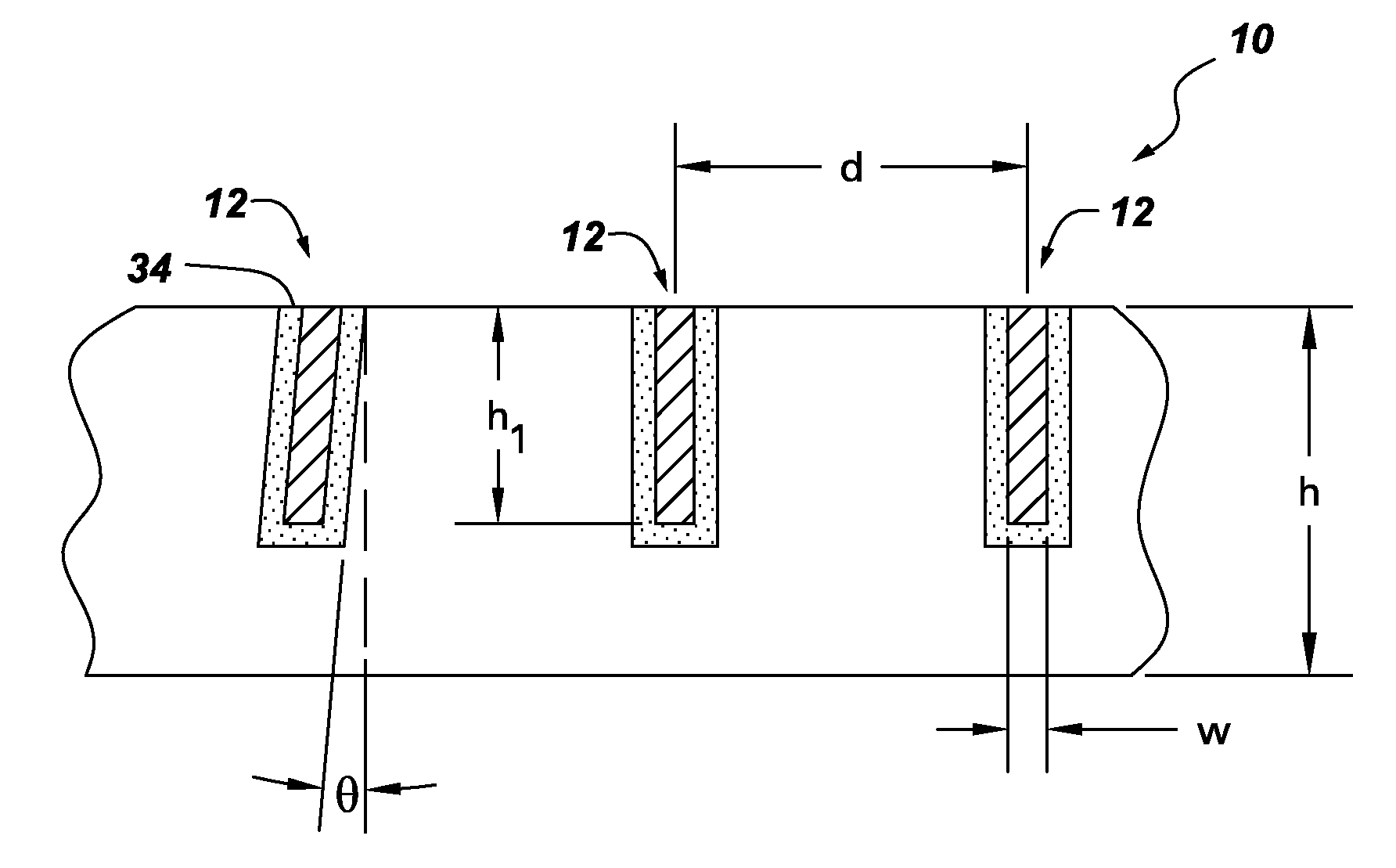
[0018]Aspects of the present invention have been shown to offer advantages over previous methodologies of making anti-scatter X-ray grid devices. Aspects of the present invention provide a manufacturing technique that allows for thinner grid lines and highly X-ray transparent interspace material in a cost effective and well-controlled process. Amongst other advantages, use of grid devices 10 employing the present invention will provide for better imaging results for mammographic and other low energy (e.g., about 26-33 kVp) X-ray systems.

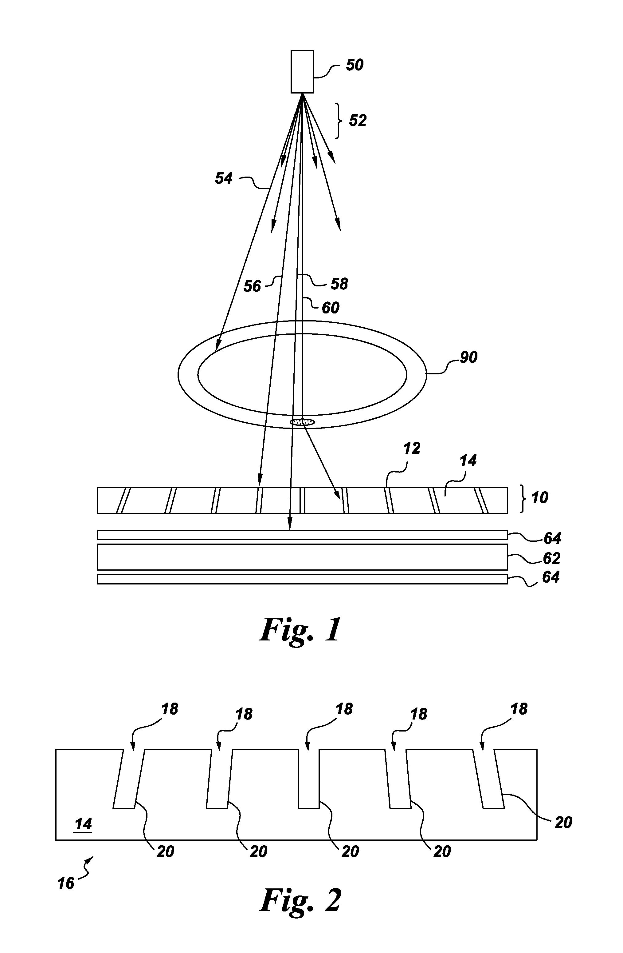
[0019]FIG. 1 is a sectional side view of a conventional radiographic imaging arrangement employing an embodiment of the present invention. A tube 50 generates and emits x-radiation 52 which travels toward a body 90. Some of the x-radiation 54 is absorbed by the body 90 while some of the radiation penetrates and travels along paths 56 and 58 as primary radiation, and other radiation is deflected and travels along path 60 as scattered radiation.

[0020]R...


PUM


Abstract

A method of making an anti-scatter X-ray grid device, and the X-ray grid device made therefrom, includes providing a substrate made of a material substantially non-absorbent of X-rays that includes channels therein; applying a layer, also of a substantially non-absorbent of X-rays material, onto a sidewall(s) of the channels, wherein the layer comprises a second material; and then applying a material substantially absorbent of X-rays into a portion of the channels, so as to define a plurality of X-ray absorbing elements. The present invention has been described in terms of specific embodiment(s), and it is recognized that equivalents, alternatives, and modifications, aside from those expressly stated, are possible and within the scope of the appending claims.

Description

BACKGROUND OF THE INVENTION[0001]The present invention relates generally to the field of diagnostic radiography and, more particularly, to an anti-scatter X-ray grid device and a method of making the same.[0002]Anti-scatter grids are widely used in X-ray imaging to enhance image quality. X-rays emitted from a point source pass through a patient or object and are then detected in a suitable X-ray detector. X-ray imaging works by detecting the intensity of X-rays as a function of position across the X-ray detector. Darker areas with less intensity correspond to regions of higher density or thickness in the object, while lighter areas with greater intensity correspond to areas of lower density or thickness in the object. This method relies on X-rays either passing directly through the object or being totally absorbed. However, X-rays may also undergo scattering processes, primarily Compton scattering, in the patient or object. Such X-rays generate image noise and thus reduce the qualit...

Claims


Application Information

Patent Timeline
Patent Type & Authority Patents(United States)
IPC IPC(8): G21K1/00
CPCG21K1/025
Inventor SHAW, JEFFREY JONDUROCHER, KEVIN MATTHEW
Owner GENERAL ELECTRIC CO
Why Eureka
Try Eureka