Pipe cutter

a technology of power tools and pipe cutters, which is applied in the direction of turning machine accessories, manufacturing tools, and tube shearing machines, etc., can solve the problems of imperfect cuts, time-consuming and labor-intensive manual intervention, and the method of cutting oftentimes requires manual intervention

Active Publication Date: 2012-09-18
MILWAUKEE ELECTRIC TOOL CORP
View PDF208 Cites 32 Cited by
  • Summary
  • Abstract
  • Description
  • Claims
  • Application Information

AI Technical Summary

Problems solved by technology

However, these methods of cutting oftentimes require manual intervention at some point during the cutting process, including, for example, loading a pipe within the pipe cutter, adjusting the pipe cutter to accommodate different pipe sizes, and applying a cutting force to the pipe.
Such manual intervention can be time consuming and result in imperfect cuts.

Method used


Image

  • Pipe cutter
  • Pipe cutter
  • Pipe cutter

Examples


Embodiment Construction

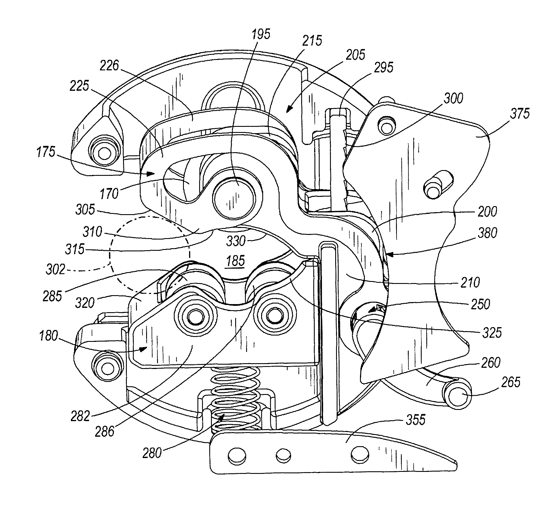
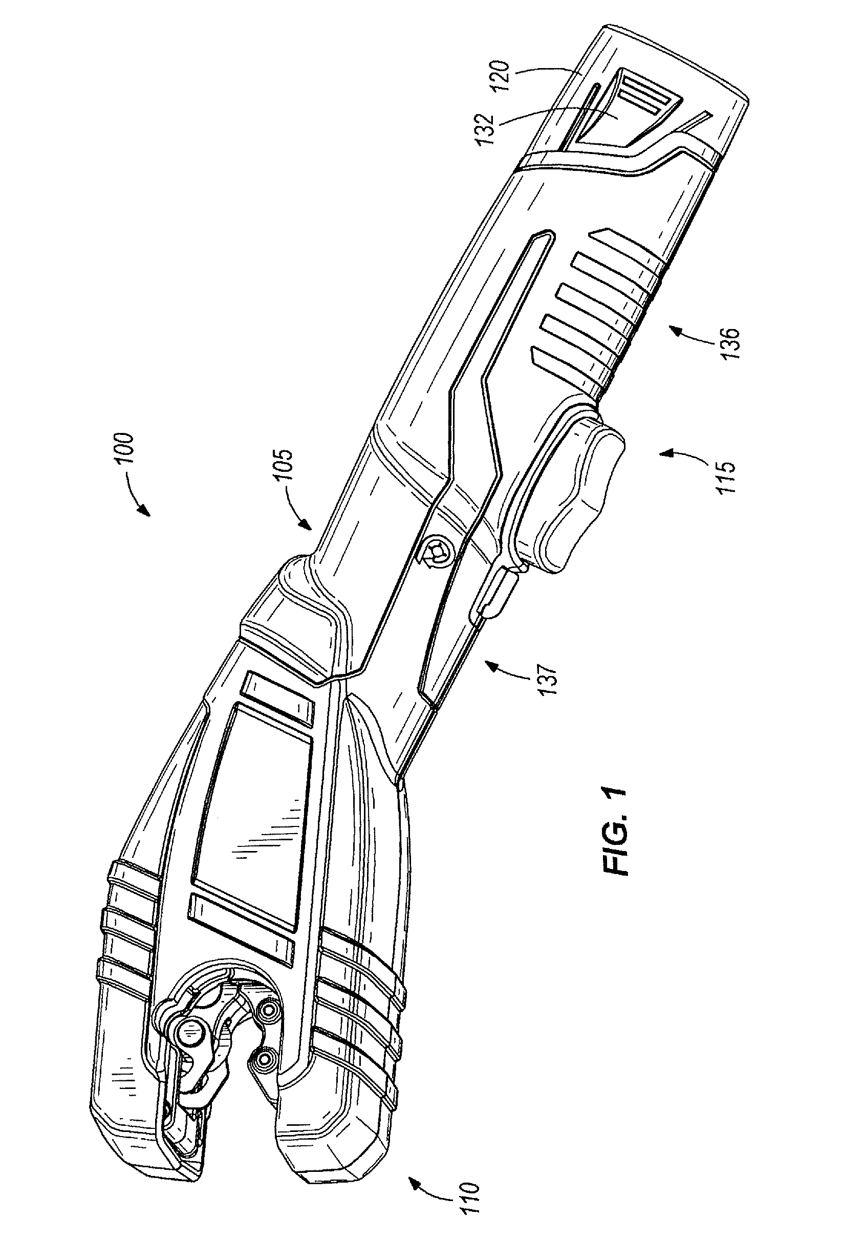
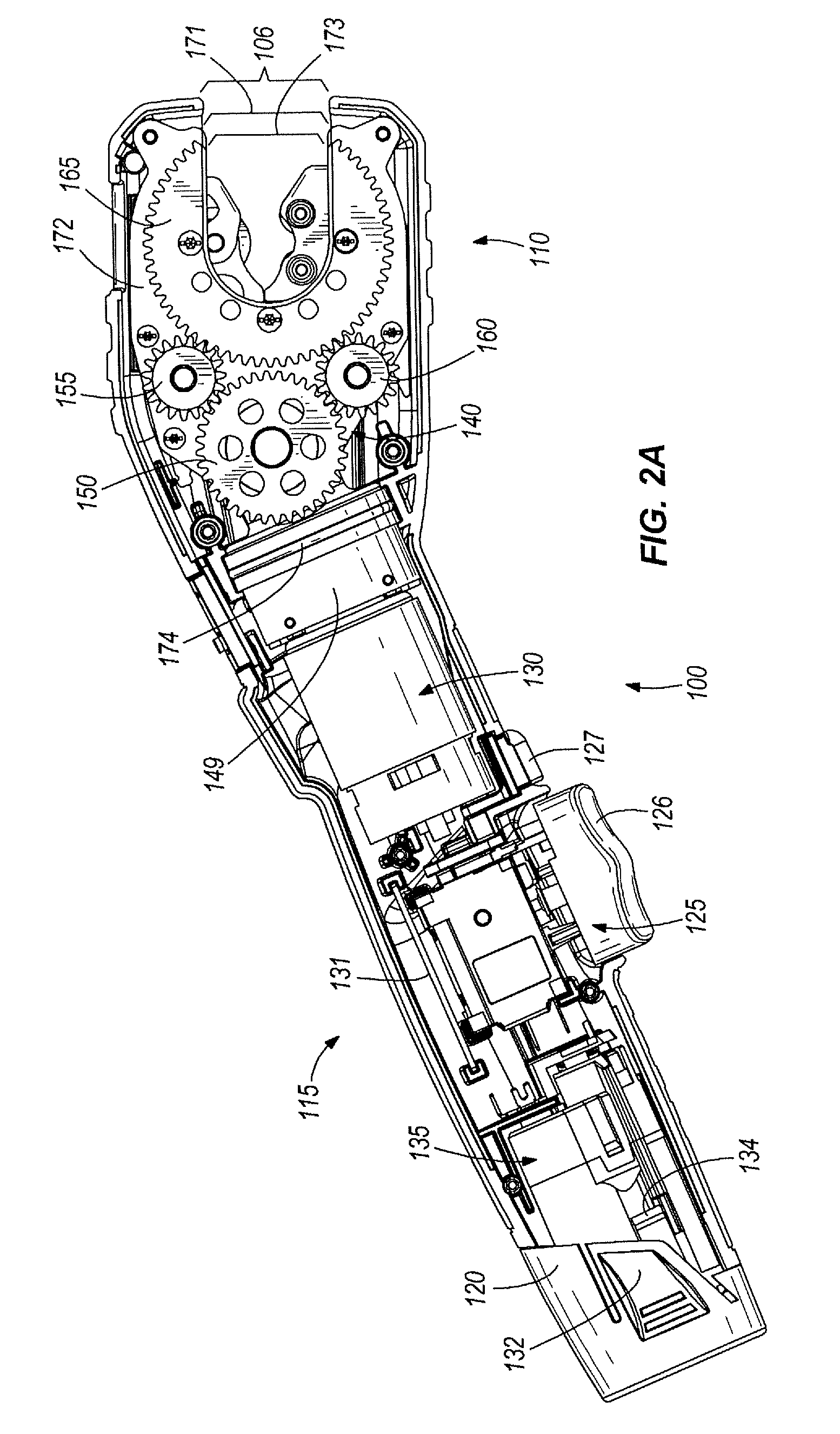
[0032]FIGS. 1-12 show a pipe cutter 100 according to one embodiment of the invention. The pipe cutter 100 is a hand-held, battery-operated pipe cutter, although according to another embodiment, the pipe cutter 100 may be a corded pipe cutter. The pipe cutter 100 is configured to cut a variety of pipe sizes and materials. In the illustrated embodiment, the pipe cutter is configured to cut metal pipes having ⅜ inch through 1 inch nominal inner diameter (i.e., ½ inch to 1⅛ inch outer diameter). Such metal pipes may include any type of copper having thicknesses K, L, and M, electric metallic tubing (conduit) of ¾ inch and 1 inch, aluminum, brass, and other metal pipes.

[0033]The pipe cutter 100 includes a housing 105 having a forward portion 110 and a handle portion 115. The housing 105 forms an exterior of the pipe cutter 100 and contains various mechanical and / or electrical components of the pipe cutter 100. The housing 105 may be a hard plastic material, a metal material, and / or any o...


PUM

PropertyMeasurementUnit
outer diameteraaaaaaaaaa
thicknessesaaaaaaaaaa
voltageaaaaaaaaaa

Abstract

A pipe cutter for cutting a pipe includes a cutting head assembly having a first carriage and a second carriage spaced apart to define a cutting area. The first carriage supports a cutting mechanism, and the second carriage is configured to support a pipe within the cutting area. The carriages have a locked state and an unlocked state such that when the carriages are in the unlocked state, the carriages are movable relative to each other and biased into the cutting area. The pipe cutter also includes a drive assembly configured to rotate the cutting head assembly and a locking mechanism configured for changing the carriages from the unlocked state to the locked state and for holding the carriages in the locked state. The locking mechanism includes an actuation member rotatably coupled to the first carriage.

Description

CROSS-REFERENCE TO RELATED APPLICATIONS[0001]The present patent application claims priority to U.S. Provisional Patent Application Ser. No. 60 / 895,062, titled “PIPE CUTTER” filed on Mar. 15, 2007, and also claims priority to U.S. Provisional Patent Application Ser. No. 60 / 990,862, titled “PIPE CUTTER” filed on Nov. 28, 2007, the entire contents of both are hereby incorporated by reference.BACKGROUND OF THE INVENTION[0002]The present invention relates generally to a cordless power tool and more specifically, to a battery-powered pipe cutter.[0003]Power-operated pipe cutters perform cutting operations in a variety of manners, many of which are largely automated. However, these methods of cutting oftentimes require manual intervention at some point during the cutting process, including, for example, loading a pipe within the pipe cutter, adjusting the pipe cutter to accommodate different pipe sizes, and applying a cutting force to the pipe. Such manual intervention can be time consumin...

Claims


Application Information

Patent Timeline
Patent Type & Authority Patents(United States)
IPC IPC(8): B23D21/08
CPCB23D21/04B23D21/08Y10T82/16918Y10T82/16541B26D3/169
Inventor THORSON, TROY C.ALBERTI, DANIEL J.BEDNAR, THOMAS R.SCOTT, JOHN S.ANDERSON, SCOTT
Owner MILWAUKEE ELECTRIC TOOL CORP
Why Eureka
Try Eureka