Outer operational device for panic exit door lock

a technology for exiting doors and operating devices, which is applied in the direction of mechanical equipment, door/window fittings, mechanical controls, etc., can solve the problems of inconvenient installation and troublesome installation

Active Publication Date: 2012-09-18
I TEK METAL MFG
View PDF34 Cites 15 Cited by
  • Summary
  • Abstract
  • Description
  • Claims
  • Application Information

AI Technical Summary

Problems solved by technology

However, troublesome installation is required when mounting the door locks to a differently handed door.
In this case, detachment of the whole door lock is required, leading to inconvenient installation.

Method used


Image

  • Outer operational device for panic exit door lock
  • Outer operational device for panic exit door lock
  • Outer operational device for panic exit door lock

Examples


Embodiment Construction

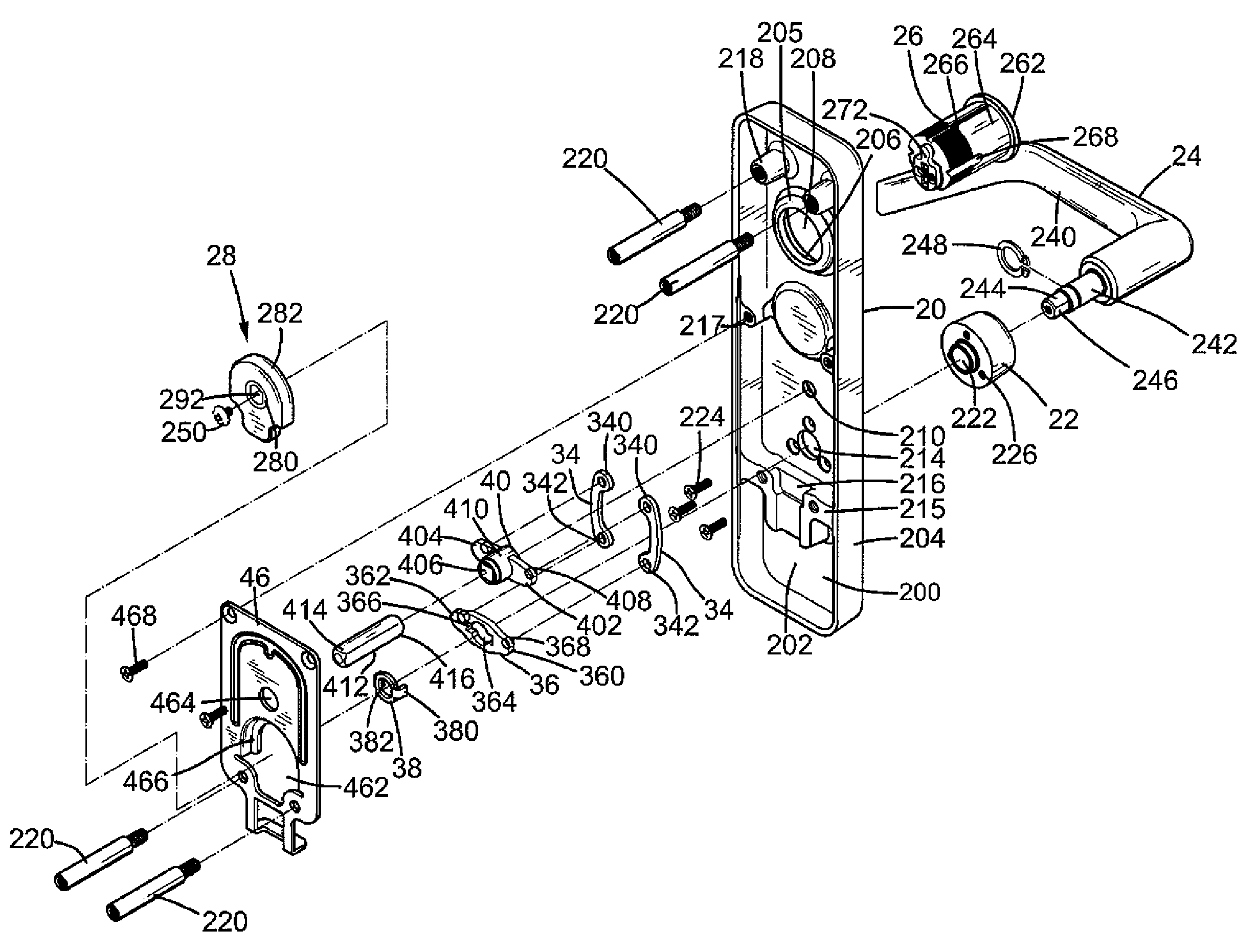
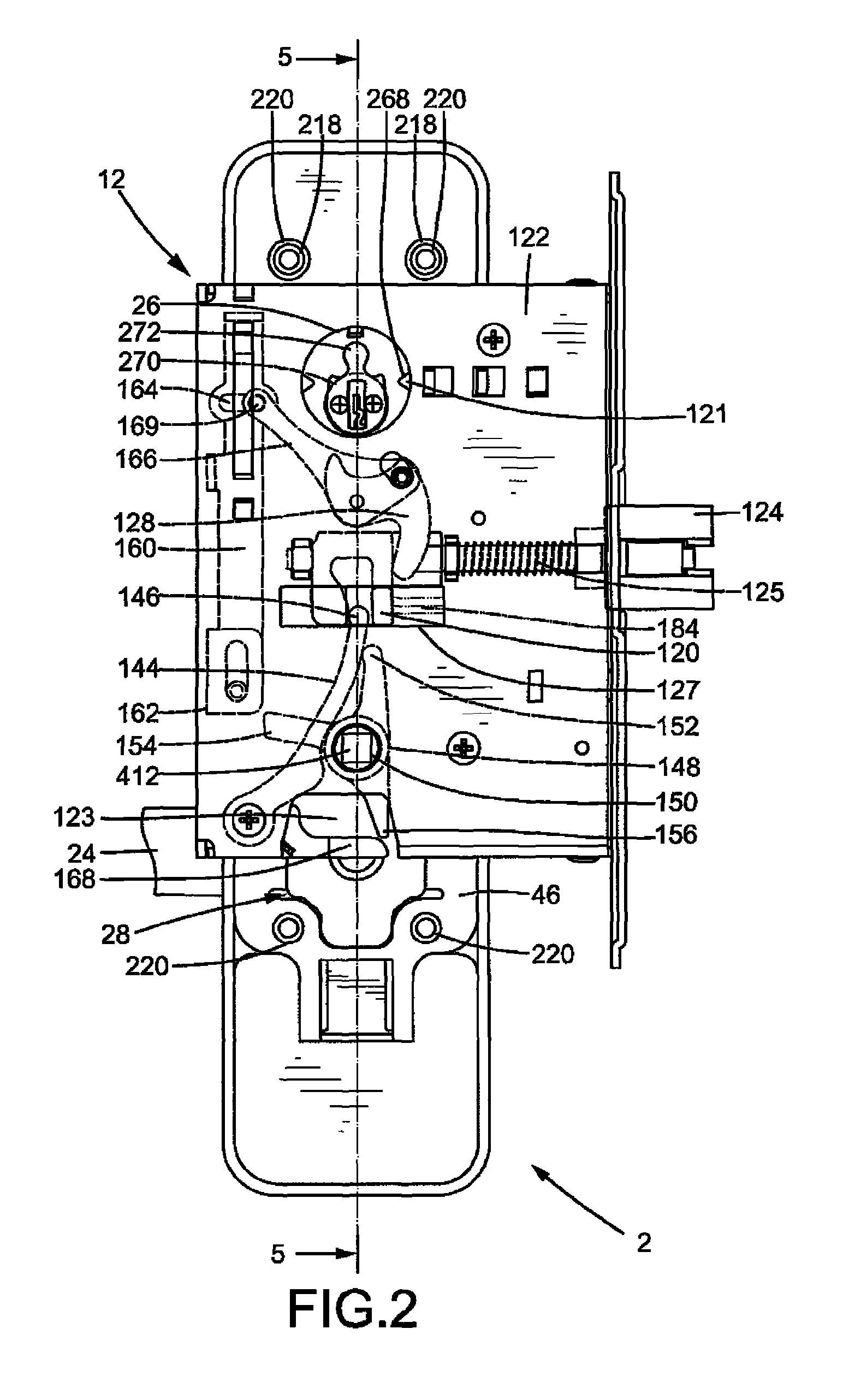
[0025]An outer operational device according to the preferred teachings of the present invention is shown in the drawings and generally designated 2 and adapted to be mounted to a side of a door 10. According to the preferred form shown, door 10 includes an inner side 10a and an outer side 10b. It is noted that inner and outer sides 10a and 10b are exchanged when door 10 is installed as a differently handed door. According to the most preferred form shown in FIG. 1, door 10 is installed as a right-handed door. Furthermore, door 10 includes a mounting hole 105 in an edge extending between inner side 10a and outer side 10b. Door 10 further includes a plurality of first holes 102 extending from inner side 10a through outer side 10b. Door 10 further includes a second hole 104 and a third hole 106 in outer side 10b and a fourth hole 107 in inner side 10a. Each of holes 102, 104, 106, and 107 is in communication with mounting hole 105. A lock 12 in the most preferred form shown as a mortis...


PUM


Abstract

An outer operational device includes a cover mounted to a side of a door. An actuating member is mounted in the cover and includes an end engaged with a handle to rotate therewith. A driving member is pivotably received in the cover and includes a wing. A link includes an upper end pivotably coupled with the wing and a lower end pivotably coupled with an end of the actuating member. A driving rod is coupled with the driving member and operably connected to a latch of a lock mounted in the door, so that rotation of the handle causes retraction of the latch.

Description

BACKGROUND OF THE INVENTION[0001]The present invention relates to an outer operational device for a panic exit door lock and, more particularly, to an outer operational device for a panic exit door lock that includes a handle for unlocking purposes.[0002]Panic exit door locks of the type having a latch extending through a vertical, lateral side of a door generally include inner and outer operational devices that can be operated to unlock the door. However, troublesome installation is required when mounting the door locks to a differently handed door. To allow slight adjustment of positions of the inner and outer operational devices during on-site installation, the door generally includes a plurality of through-holes through which mounting posts are extended. The through-holes have diameters larger than those of the mounting posts such that the latch may not be completely retracted for unlocking purposes. In this case, detachment of the whole door lock is required, leading to inconve...

Claims


Application Information

Patent Timeline
Patent Type & Authority Patents(United States)
IPC IPC(8): E05B65/10
CPCE05B3/00E05B3/065E05B15/02E05B53/00Y10T292/0839Y10T292/0909Y10T292/0971Y10T292/1014
Inventor TIEN, HUNG-JENHUANG, CHEN-WEI
Owner I TEK METAL MFG
Why Eureka
Try Eureka