
Door lock apparatus for vehicle

a door lock and vehicle technology, applied in the direction of passenger lock actuation, lock application, anti-theft devices, etc., can solve the problems of deteriorating the operation feeling of the inside handle, and reducing the transmission efficiency of the operation force of the inside handl

Active Publication Date: 2012-09-18
AISIN SEIKI KK
View PDF13 Cites 20 Cited by
  • Summary
  • Abstract
  • Description
  • Claims
  • Application Information

AI Technical Summary

Benefits of technology

The present invention is a door lock apparatus for a vehicle that includes a latch mechanism, an open operation lever, an open lever, a locking lever, a link operation lever, a link member, and a lever member. The link member can transmit the operation of the open lever to the latch mechanism when the locking lever is in the unlocked position, and the latch mechanism can bring the vehicle door to be in an open ready state relative to the vehicle body. The link member cannot transmit the operation of the open lever to the latch mechanism when the locking lever is in the locked position. The lever member can move the locking lever from the locked position to the unlocked position by means of the operation of the open lever. The technical effect of this invention is to improve the safety and convenience of the vehicle door lock system.

Problems solved by technology

In this case, since the transmission path is constituted by three members, the transmission efficiency of the operation force may be reduced, which may lead to deterioration in the operation feeling of the inside handle.
However, even when the door lock apparatus is applied to such type of door, the aforementioned transmission path is constituted by two members, which may still lead to the decrease in the transmission efficiency of the operation force of the inside handle.

Method used


Image

  • Door lock apparatus for vehicle
  • Door lock apparatus for vehicle
  • Door lock apparatus for vehicle

Examples


Embodiment Construction

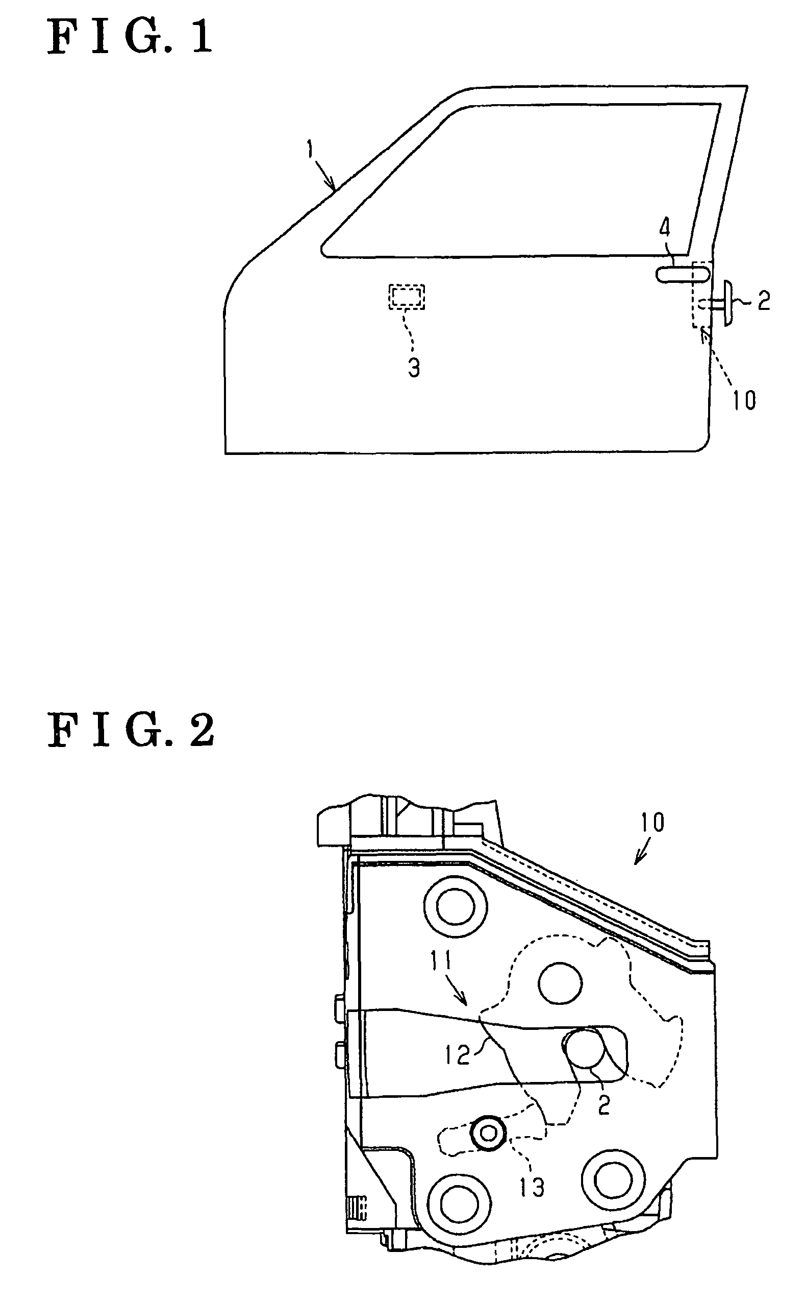
[0020]An embodiment of the present invention will be explained with reference to the attached drawings. As illustrated in FIG. 1, a door lock apparatus 10 is provided within a vehicle door 1, specifically, in the vicinity of a rear edge thereof. The door lock apparatus 10 holds the vehicle door 1 in a closed state relative to a vehicle body (not shown) by an engagement with a striker 2 provided at the vehicle body. An inside handle 3 serving as a door handle is arranged at the vehicle door 1 so as to be exposed to an interior of a vehicle. An outside handle 4 is also provided at the vehicle door 1 so as to be exposed to an exterior of the vehicle.

[0021]As illustrated in FIG. 2, the door lock apparatus 10 includes a latch mechanism 11 having a latch 12 and a pawl 13. The latch mechanism 11 engages with the striker 2, thereby retaining the closed state of the vehicle door 1 relative to the vehicle body. That is, when closing the vehicle door 1, the latch 12 rotates to engage with the ...


PUM


Abstract

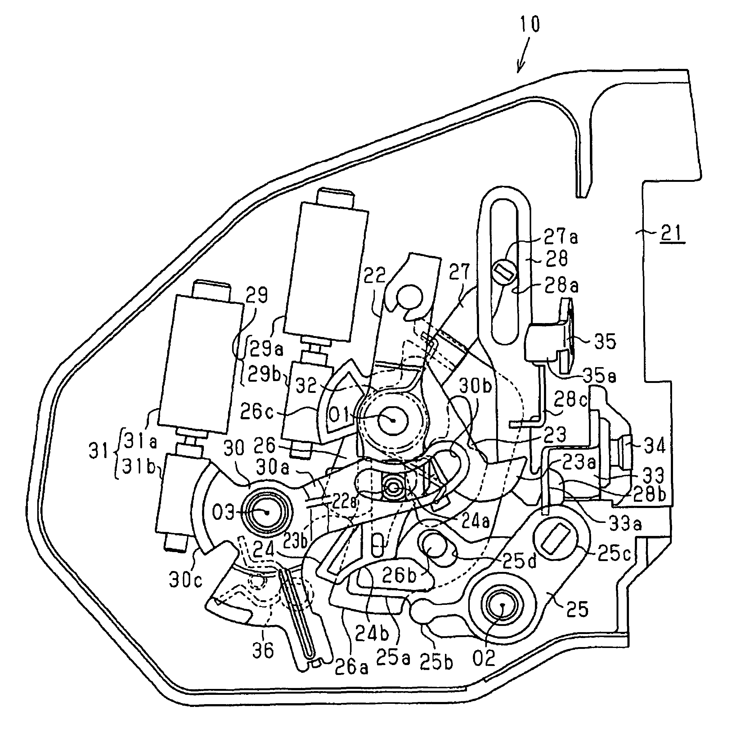
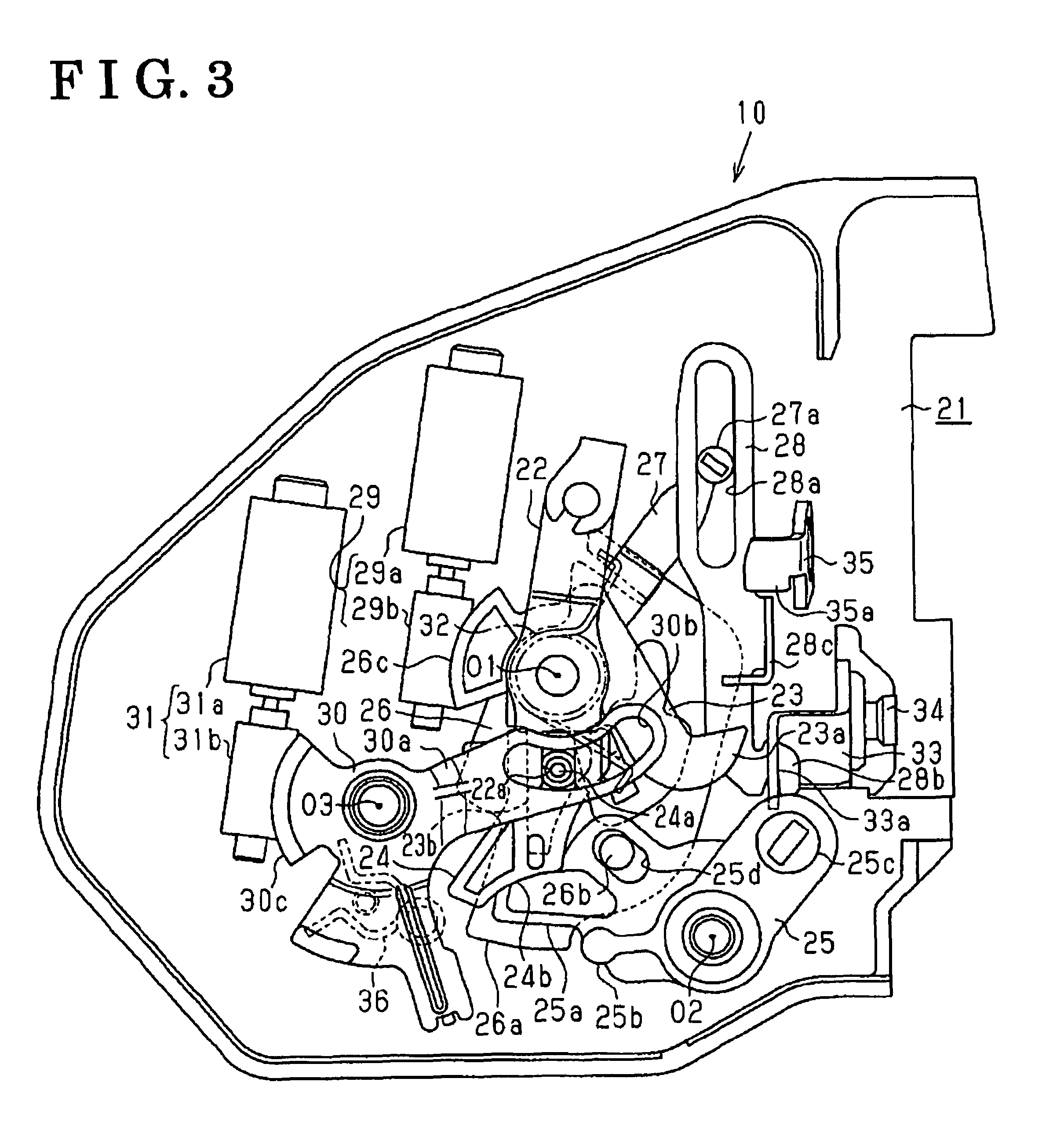
A door lock apparatus for a vehicle includes a latch mechanism, an open operation lever, an open lever operatively connected to the open operation lever, a locking lever being switchable between an unlocked position and a locked position, a link operation lever operatively connected to the locking lever, a link member operatively connected to the link operation lever, the link member being able to transmit an operation of the open lever to the latch mechanism when the locking lever is in the unlocked position, the link member being unable to transmit the operation of the open lever to the latch mechanism when the locking lever is in the locked position, and a lever member operatively connected to the open lever and the locking lever, the lever member moving the locking lever from the locked position to the unlocked position by means of the operation of the open lever.

Description

CROSS REFERENCE TO RELATED APPLICATIONS[0001]This application is based on and claims priority under 35 U.S.C. §119 to Japanese Patent Application No. 2007-218264, filed on Aug. 24, 2007, the entire content of which is incorporated herein by reference.FIELD OF THE INVENTION[0002]This invention generally relates to a door lock apparatus for a vehicle.BACKGROUND[0003]A known door lock apparatus for a vehicle is disclosed, for example, in JP2004124687A. According to the door lock apparatus disclosed, a locked state and an unlocked state of a vehicle door relative to a vehicle body are switched in a state where the vehicle door is retained in a closed state relative to the vehicle body by means of a latch mechanism. In the unlocked state, the vehicle door can be opened, i.e., the closed state of the vehicle door can be cancelled, by an operation of a door handle. In the locked state, the vehicle door cannot be opened, i.e., the closed state of the vehicle door cannot be cancelled, by the...

Claims


Application Information

Patent Timeline
Patent Type & Authority Patents(United States)
IPC IPC(8): E05C3/06E05C3/16E05B85/24E05B77/30E05B79/10
CPCE05B77/26E05B77/30E05B81/36E05B81/16E05B83/36E05B81/06E05B77/32Y10T70/5889Y10T292/1045Y10T292/1047Y10T292/1082Y10T292/57
Inventor AKIZUKI, RYUJIRONISHIO, TAKASHISEO, KAZUMASAYAMADA, YUSUKE
Owner AISIN SEIKI KK
Learn More