Optical triangulation sensor

a triangulation sensor and optical technology, applied in the field of measurement equipment, can solve the problems of difficult identification of the location of the edges of each panel, difficult identification of the specific measurement point from the image, and difficulty in measuring certain surfaces or objects, etc., to achieve accurate and repeatable calculation, accurate location and orientation of the sensor

Active Publication Date: 2012-09-25
THIRD DIMENSION SOFTWARE
View PDF13 Cites 5 Cited by
  • Summary
  • Abstract
  • Description
  • Claims
  • Application Information

AI Technical Summary

Benefits of technology

[0013]By restricting the line of light projecting from the measurement device to form a predetermined pattern it may be possible to measure features which would be otherwise impossible or difficult to measure consistently. The limitation of the planar illumination source can allow unwanted features within the measurement view to be omitted from the measurement, and may provide a reference point in the image for permitting consistent identification of features on the measurement surface.
[0051]The aperture may be round, e.g. substantially circular, for fitting around a head of a fastener. In the case of measuring fasteners, the outward facing head of the fastener often has a series of depressions stamped or otherwise formed into its surface. These depression should be ignored when measuring the overall proud / recess / angle fit of the fastener. The marker(s) of the invention may permit the edges of the fastener to be distinguished in an automated fashion from the depressions. This permits consistent analysis of the condition (proud / recess) at the edges of the fastener and can also enable more accurate and repeatable calculation of the angle of the fastener head relative to the measurement surface.

Problems solved by technology

The measurement of certain surfaces or objects can be difficult due to the arrangement or complexity of the objects being measured.
This condition may make it difficult to identify the location of the edges of each panel 10, 11 from the image captured by a camera of an optical triangulation sensor (not shown).
In this case it can be difficult to identify the specific measurement point from the image when the data contains several possible measurement conditions.
This problem may be typical of measurement of features on automotive interior fascia panels.

Method used


Image

  • Optical triangulation sensor
  • Optical triangulation sensor
  • Optical triangulation sensor

Examples


Embodiment Construction

; FURTHER OPTIONS AND PREFERENCES

[0069]Each of the embodiments discussed below may be applied as an enhancement to a conventional optical triangulation sensor, e.g. the GapGun sensor manufactured by Third Dimension Software Limited, mentioned above.

Multiple Beam Emitter

[0070]FIGS. 6, 7 and 8A-8F relate to the first aspect of the invention. In the embodiments discussed below, a plurality of coplanar spatially separated planar light beams are produced from a conventional laser triangulation sensor by locating a mask at the output of the light source to block portions of a generated planar light beam.

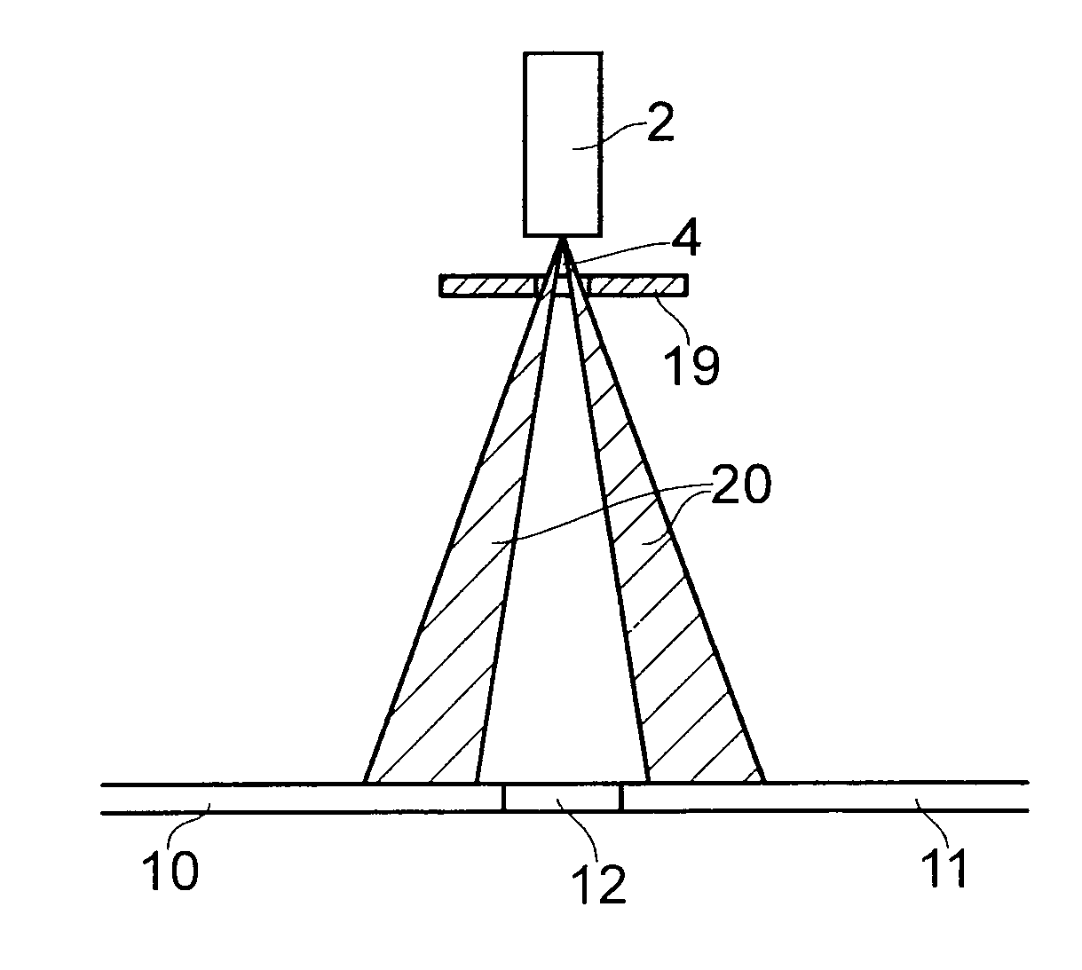
[0071]FIG. 6 shows a mask 19 that is suitable for use in the invention. In this embodiment, the mask 19 is made from a plate of opaque material (e.g. plastic, metal, glass or the like) with an arrangement of apertures 18 machined therethrough. Alternatively, the plate may be clear, and the apertures formed by suitable printing opaque material thereon. The mask may be made of partially opaq...


PUM


Abstract

An optical, such as a laser, triangulation sensor is disclosed in which a configuration of an output light beam is controlled using a mask in front of a light source. The configuration may include a plurality of coplanar spatially separated planar light beams. The mask may be movable to provide different light beam configurations. Masking parts of the light beam enables unwanted features on the measurement surface to be omitted. Also disclosed is a guide element for an optical sensor for facilitating hole diameter measurement. The guide element has contact surfaces lying on a virtual conical surface which abut the hole edge to enable consistent placement of the light beam with respect to the hole centre. Also disclosed is a guide element for an optical sensor having an aperture for framing surface features, such as a rivert to permit accurate location of the light beam therewith.

Description

FIELD OF THE INVENTION[0001]This invention relates to measurement apparatus which uses triangulation principles to measure the physical geometry of articles and / or their relative position to each other. For example, the invention may be used with a laser triangulation sensor.BACKGROUND TO THE INVENTION[0002]Optical measurement systems which use a laser triangulation sensor to obtain dimensional information about objects are known. For example, such systems may be arranged to determine the distance of objects from the sensor or the profile of objects within the field of view of the sensor.[0003]Referring to FIG. 1, a conventional laser triangulation measurement device 1 comprises a light source 2 e.g. laser which is arranged to project a planar beam 4 (e.g. sheet) of light. The planar beam 4 is incident as a line 8 on an object or objects 5, 6 which lie in the field of view 7 of the device 1. Light reflected from the incident line 8 is collected by an imaging device 3, which may be a...

Claims


Application Information

Patent Timeline
Patent Type & Authority Patents(United States)
IPC IPC(8): G01B11/24
CPCG01B11/25
Inventor MONKS, TIMROBINSON, STEVE
Owner THIRD DIMENSION SOFTWARE
Why Eureka
Try Eureka