Optical triangulation device and method of measuring a variable of a web using the device

a triangulation device and web technology, applied in measurement devices, instruments, scientific instruments, etc., can solve problems such as high frequency variations, holes or tears, and devices with parts, and achieve the effect of avoiding inaccuracy and high frequency variations

Inactive Publication Date: 2008-03-18
VOITH PATENT GMBH
View PDF5 Cites 2 Cited by
  • Summary
  • Abstract
  • Description
  • Claims
  • Application Information

AI Technical Summary

Benefits of technology

[0012]The invention avoids the inaccuracy that results from light scattering from inside the sheet by concentrating on surface features. These surface features cause high frequency variations in the reflected light, especially at specular angles. Thus, light reflected from the surface can be detected separately from the overall reflectance by observing the high frequency signals from the detector system.
[0015]By finding the position of the high frequency component of the spot image, the position of the surface of the paper can be isolated. This eliminates error cause by averaging all frequencies, which include components of the image from deeper into the sheet.
[0037]The invention also provides for a method of determining a position of an uppermost portion of an irregular surface of a web relative to a reference position, wherein the method comprises producing a light, focusing, with a first lens arrangement, the light into a tightly focused spot onto the irregular surface, wherein the first lens arrangement is oriented along a first axis, focusing, with a second lens arrangement, a reflected image of the spot along a second axis onto detector elements of a detector, wherein the second axis is oriented at an angle with respect to the first axis, preventing a substantial portion of the light reflected from a position beneath the uppermost portion of the surface from being focused onto the detector elements, processing signals from the detector, calculating the position of the uppermost portion of the irregular surface based on the signals and the reference position, and at least one of displaying the position as a value, storing the position, and communicating the position to a processor.
[0040]The simultaneously determining may comprise producing another light, focusing, with a third lens arrangement, the other light into a tightly focused spot onto the other irregular surface, wherein the third lens arrangement is oriented along a third axis, focusing, with a fourth lens arrangement, a reflected image of the spot along a fourth axis onto detector elements of another detector, wherein the third axis is oriented at an angle with respect to the fourth axis, preventing a substantial portion of the light reflected from a position beneath the oppositely facing uppermost portion from being focused onto the detector elements of the other detector, processing signals from the other detector, calculating the position of the oppositely facing uppermost portion of the other irregular surface based on the signals and the other reference position, at least one of displaying the position as a value, storing the position, and communicating the position to a processor, and determining a thickness of the web based on the positions of the oppositely facing uppermost portions of the web.

Problems solved by technology

There are disadvantageous with using a device with parts which touch the sheet, i.e., with a device which uses contact measurement.
The main disadvantage of the device is that on fast moving sheets, such contact can produce holes or tears.
These holes or tears occur when an imperfection in the sheet, such as grit, hits the caliper sensor.
Then, if paper sheet with a hole reaches, e.g., a printing press, the hole can cause a costly sheet break that typically stops the press for several hours.
As more recycled products are used in papermaking, imperfections become a growing problem.
Besides these holes or tears, the contacting elements of the measuring device also can cause marks on a sheet.
As a result, contacting caliper measurement is not used on sensitive paper grades.
One factor, which limits the accuracy of this measurement, however, is the scattering of light into the paper.
Since paper fibers are randomly distributed, the relationship between the center of the projected light spot and the surface of the paper is inconsistent.
This inconsistency contributes to error when compared to a mechanical caliper measurement technique.
As a result, it is very difficult to determine the spot position with an accuracy that is adequate for the required 0.25 μm measurement resolution.

Method used


Image

  • Optical triangulation device and method of measuring a variable of a web using the device
  • Optical triangulation device and method of measuring a variable of a web using the device
  • Optical triangulation device and method of measuring a variable of a web using the device

Examples


Embodiment Construction

[0051]The particulars shown herein are by way of example and for purposes of illustrative discussion of the embodiments of the present invention only and are presented in the cause of providing what is believed to be the most useful and readily understood description of the principles and conceptual aspects of the present invention. In this regard, no attempt is made to show structural details of the present invention in more detail than is necessary for the fundamental understanding of the present invention, the description is taken with the drawings making apparent to those skilled in the art how the forms of the present invention may be embodied in practice.

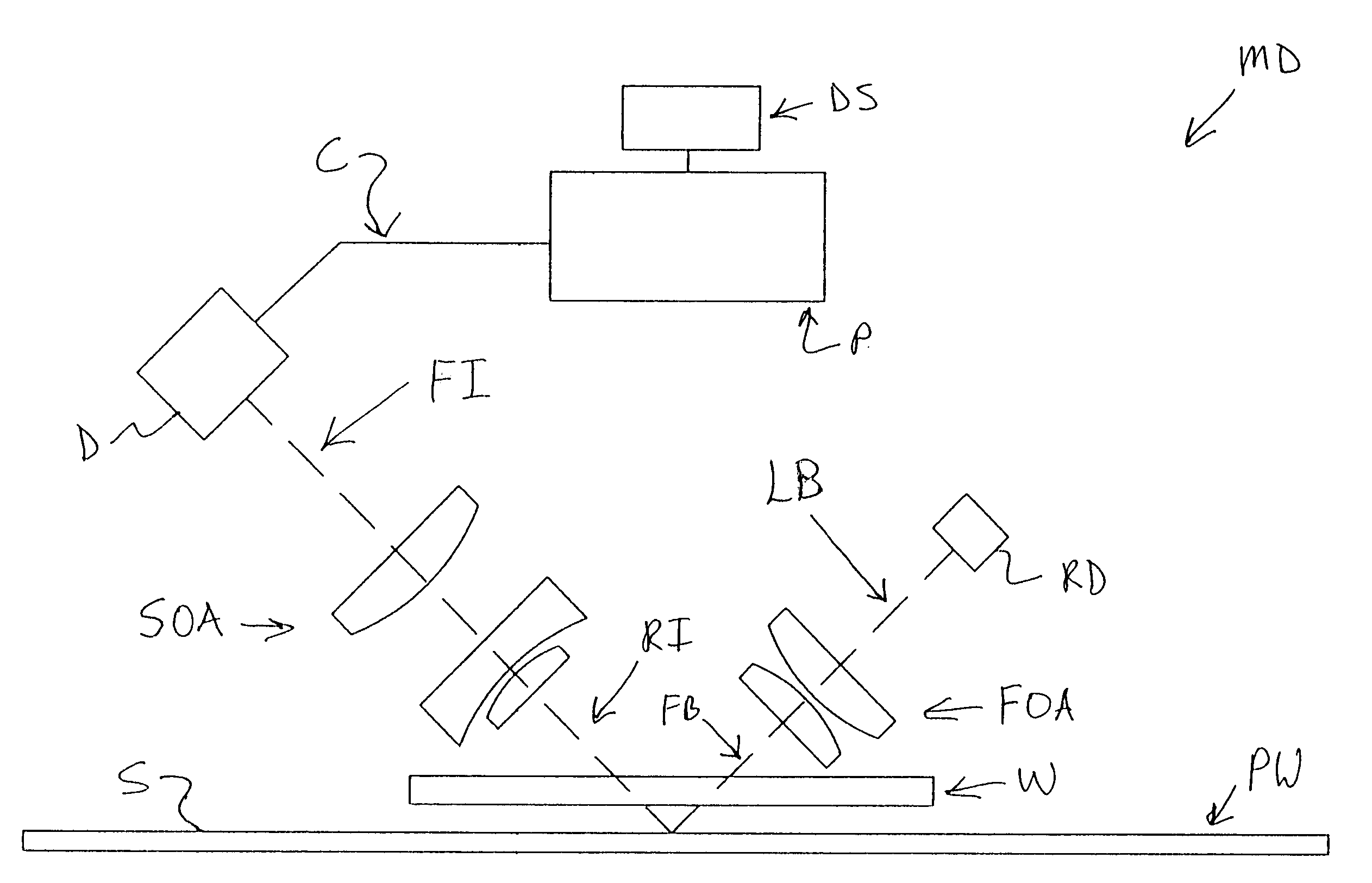
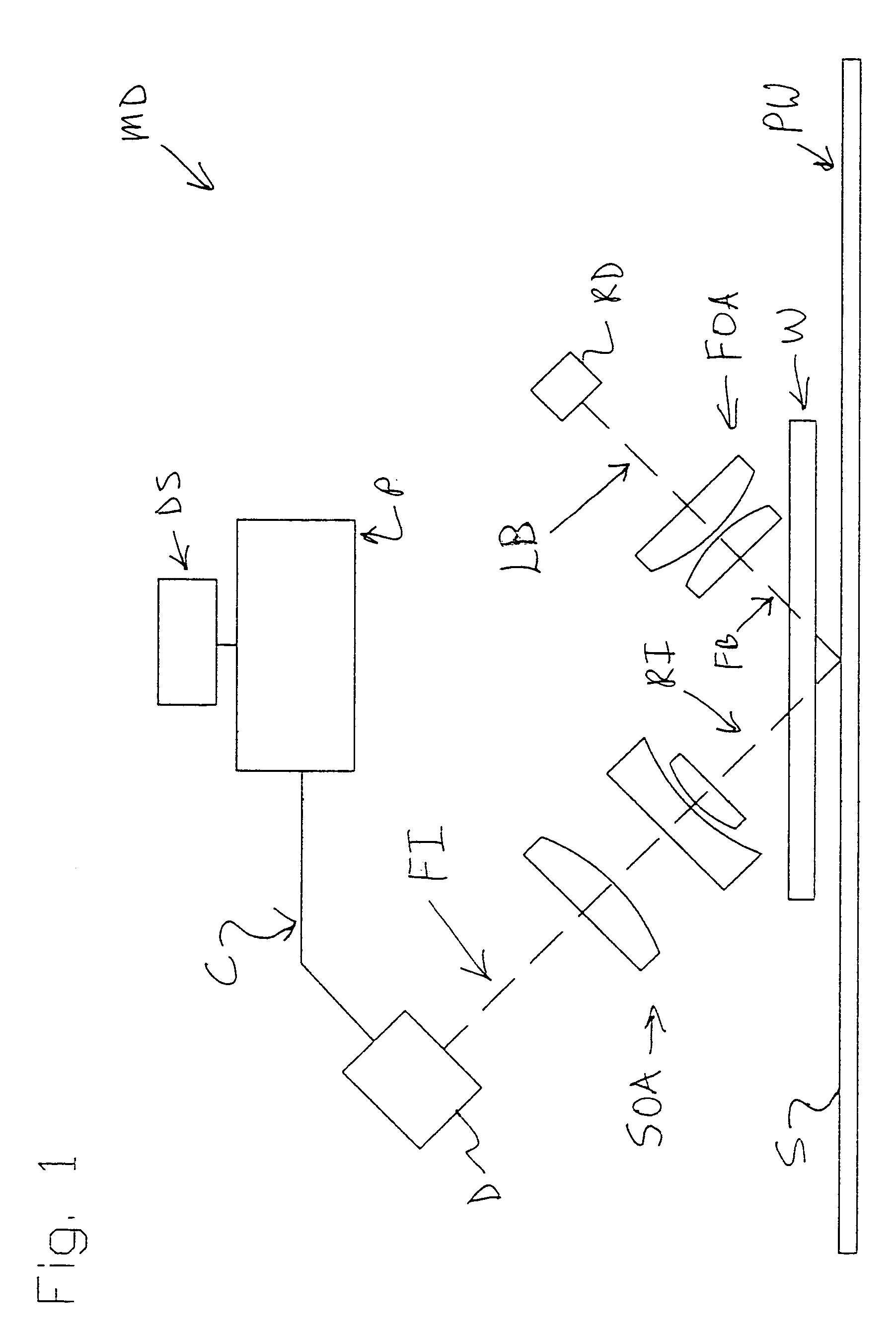
[0052]FIG. 1 shows one non-limiting embodiment of a measuring device MD according to the invention. The device MD includes electromagnetic radiation producing device RD which can have the form of, e.g., a laser, a laser diode, or an incandescent bulb with a pinhole aperture. A laser light source is preferred because of its rel...


PUM


Abstract

Device and method of measuring a position of an irregular surface. The method includes projecting a spot along a first axis onto the irregular surface, focusing an image of the spot along a second axis onto a detector, wherein the second axis is non-coaxially arranged with respect to the first axis, processing signals from the detector, and calculating the position of the irregular surface based on at least one isolated desired frequency component of the signals.

Description

BACKGROUND OF THE INVENTION[0001]1. Field of the invention[0002]The invention relates to an improved triangulation device which utilizes a tightly focused-projected light spot and a high frequency position sensitive detector. The invention also relates to using such a device to indicate and / or measure a variable of a web such as surface plasticization, surface roughness, surface gloss, coating quality, surface density, mean distance between fibers of a paper web, ash content of a paper web surface, etc. The invention also relates to a method of measuring a thickness of a web, and specifically a moving web, using a triangulation device arranged on both sides of the web.[0003]2. Description of the Prior Art[0004]Optical triangulation is accomplished by a device which projects a small spot of light onto a surface. A lens, whose optical axis is at an angle to the axis of the projected light, forms an image of the spot onto a position sensitive detector. If the surface moves closer or fa...

Claims


Application Information

Patent Timeline
Patent Type & Authority Patents(United States)
IPC IPC(8): G01B11/14
CPCG01B11/026
Inventor TYPPO, PEKKA
Owner VOITH PATENT GMBH
Why Eureka
Try Eureka