Locking pliers with one or two slide bars each secured to a stationary jaw carrier

a technology of locking pliers and slide bars, which is applied in the field of pliers, can solve the problems of difficult carrying of pliers

Active Publication Date: 2012-10-16
ZHENG BO REN
View PDF11 Cites 21 Cited by
  • Summary
  • Abstract
  • Description
  • Claims
  • Application Information

AI Technical Summary

Problems solved by technology

This is disadvantageous because the pliers is difficult of carrying due to the projecting slide bar 6.

Method used


Image

  • Locking pliers with one or two slide bars each secured to a stationary jaw carrier
  • Locking pliers with one or two slide bars each secured to a stationary jaw carrier
  • Locking pliers with one or two slide bars each secured to a stationary jaw carrier

Examples


Embodiment Construction

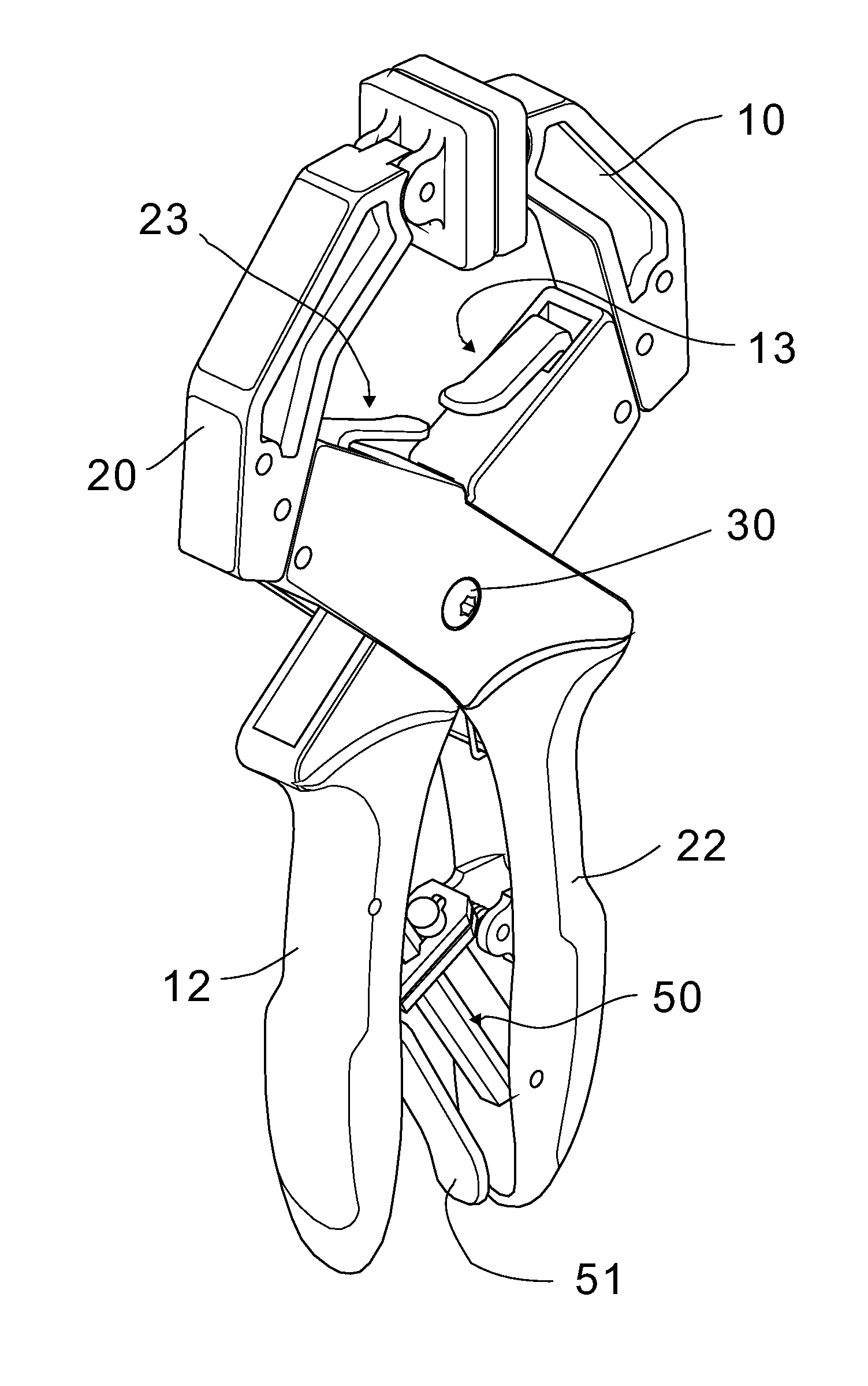
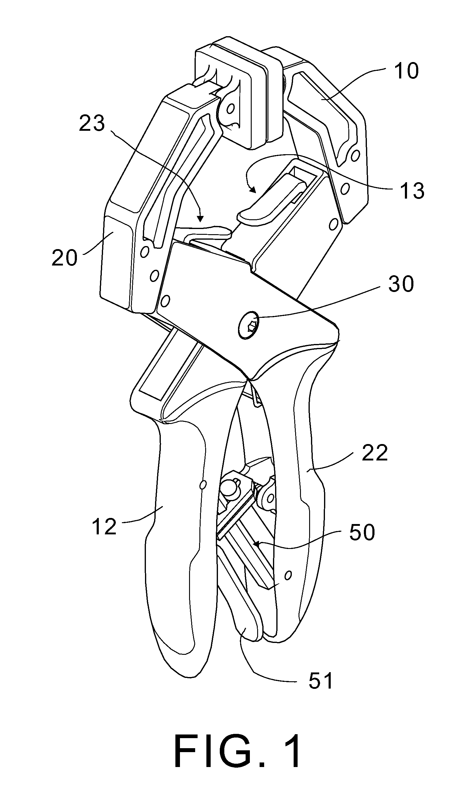
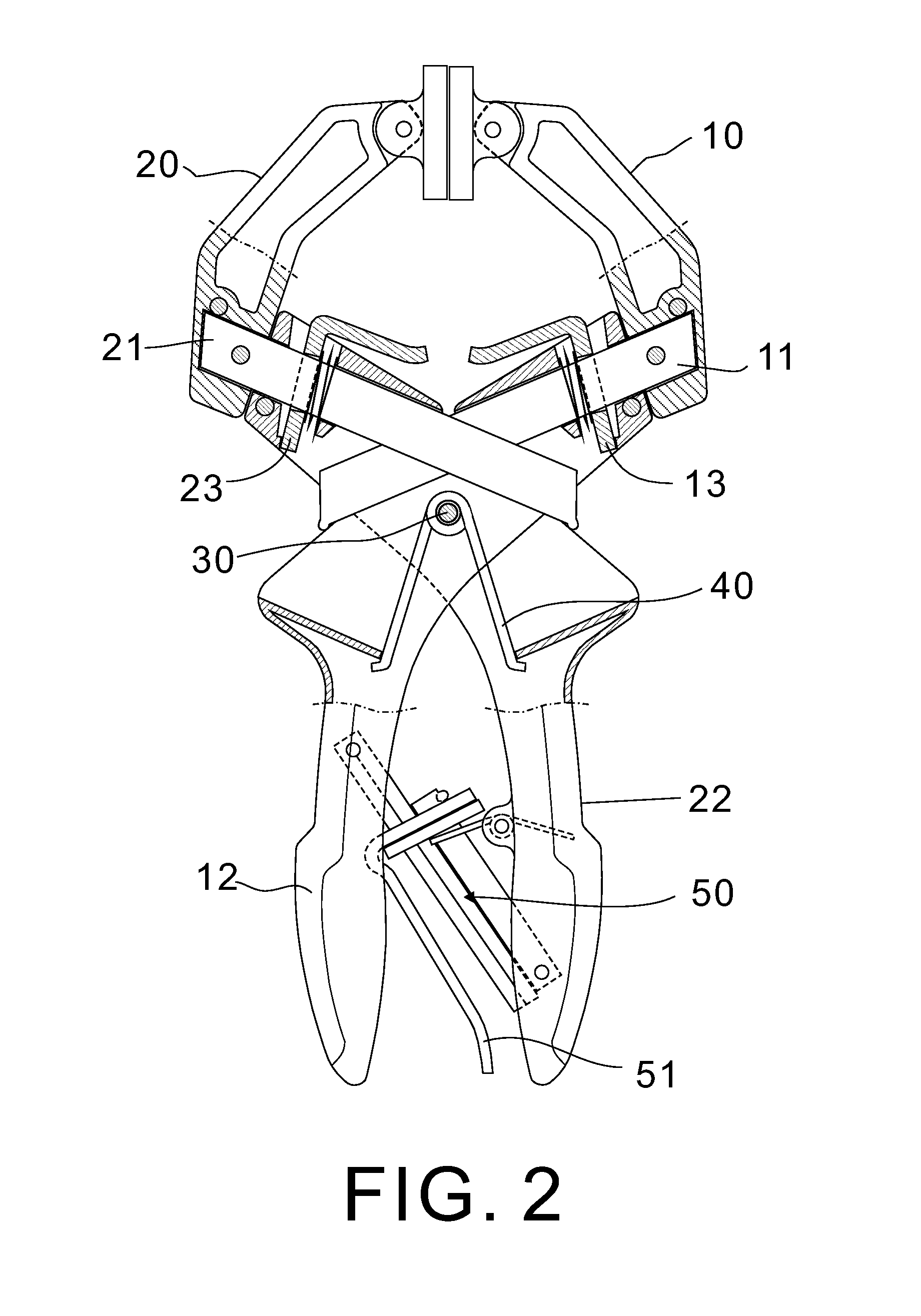
[0017]Referring to FIGS. 1 to 7, a locking pliers in accordance with the invention comprises the following components as discussed in detail below.

[0018]A first stationary jaw carrier 10 has a pivotal jaw 14 at one end. A second stationary jaw carrier 20 has a pivotal jaw 24 at one end. A bent first handle 12 and a bent second handle 22 are joined at a pivot joint 30 which is mounted with a torsion spring 40. The spring 40 has both ends anchored in two inner members of the first and second handles 12, 22 respectively so that the first and second handle 12, 22 can be resiliently pressed together.

[0019]A self-adjusting locking unit 50 is provided between the first and second handles 12, 22 and comprises a torsion spring 52 mounted on an inner surface of the second handle 22, a first bar 54 having one end pivotably secured to the inner surface of the second handle 22, a release lever 51 mounted on the other end of the first bar 54, a plate 53 urged between the other end of the spring 5...


PUM

PropertyMeasurementUnit
distanceaaaaaaaaaa

Abstract

One embodiment of a locking pliers includes a first stationary jaw carrier comprising a first jaw at one end; a second stationary jaw carrier comprising a second jaw at one end; a bent first handle integrally formed with the first stationary jaw carrier; a bent second handle joined the first handle at a spring-actuated pivot joint and engaged with the other end of the second stationary jaw carrier; a self-adjusting locking unit disposed between the first and second handles and comprising a spring-actuated release lever; a locking assembly comprising a slide bar having one end fixedly secured to the other end of the second stationary jaw carrier and the other end inserting into a portion of the second handle between the pivot joint and the other end of the second stationary jaw carrier, and a spring-actuated release lever member lockingly put on the slide bar.

Description

BACKGROUND OF THE INVENTION[0001]1. Field of Invention[0002]The invention relates to pliers and more particularly to a locking pliers having one or two slide bars each secured to a stationary jaw carrier, the slide bars being retracted in the handles when the pliers is not in use.[0003]2. Description of Related Art[0004]A typical pliers is shown in FIG. 9 and comprises a pair of handle 2, 3 joined at a fulcrum 4, a fixed first lever 5 at a front portion of the handle 2 and having a jaw 8, a slide bar 6 having one end fixedly secured to the handle 3 proximate the fulcrum 4, and a moveable second lever 7 slidably put on the slide bar 6 and having a jaw 9. In use, a user may pull the second lever 7 away from the first lever 5 or push the second lever 7 toward the first lever 5, place a work piece (not shown) in an opening between the jaws 8 and 9, and finally push the second lever 7 toward the first lever 5 to clamp the work piece.[0005]While the typical pliers is adjustable by sliding...

Claims


Application Information

Patent Timeline
Patent Type & Authority Patents(United States)
IPC IPC(8): B25B5/16
CPCB25B5/06B25B5/163B25B7/14B25B7/04Y10T29/539
Inventor ZHENG, BO REN
Owner ZHENG BO REN
Why Eureka
Try Eureka