Bicycle pannier mounting system

a technology for mounting systems and bicycles, which is applied in the direction of roofs, cycle equipments, and article supporting devices, etc., can solve the problems of limiting the functionality of the pannier system, racks having limited capacity in as much, and system drawbacks

Active Publication Date: 2012-10-23
TREK BICYCLE CORPORATION
View PDF64 Cites 31 Cited by
  • Summary
  • Abstract
  • Description
  • Claims
  • Application Information

AI Technical Summary

Benefits of technology

[0012]Another aspect of the invention usable with one or more of the aspects above is to protect the surface of the bicycle rail to which the pannier mount is attached. Preferably, a pad interacts with those portions of the hook and catch that are positioned adjacent the structure of the bicycle. Another aspect of the invention is that, while downward translation of the handle manipulates the catch so as to secure a rail member between the catch and the hook, translation of the handle in a generally upward direction disengages a stop so that the catch opens and the pannier mounting system can be removed from the bicycle.

Problems solved by technology

However, such systems are not without their respective drawbacks.
Furthermore, such supplemental packaging was often required to protect the materials from the environment associated with the ride, i.e. inclement weather conditions and / or road debris thrown up by the tires.
Furthermore, such racks had limited capacity in as much as the rider could carry as many materials as would securely remain on the rack or the basket.
Unfortunately, such mounting systems are commonly configured to interact with specific rack constructions.
Such a feature significantly limits the functionality of the pannier system by limiting the pannier to use with a given user's rail configuration.
Such systems thereby limit the use of the pannier to the bicycle equipped with the mounts lest the mounts be moved from bicycle to bicycle.
Although pannier systems having multiple clamps that are controlled by a common operator reduce the ambidexterity required to secure the pannier to the bicycle, each of the above systems can suffer from undesired disengagement of the pannier system from the bicycle.
Although a number of pannier mounting systems include latches that can secure the relative position of the pannier, such systems commonly require independent operation of the latch and / or remain susceptible to becoming loose due to road vibration or the like.

Method used


Image

  • Bicycle pannier mounting system
  • Bicycle pannier mounting system
  • Bicycle pannier mounting system

Examples


Embodiment Construction

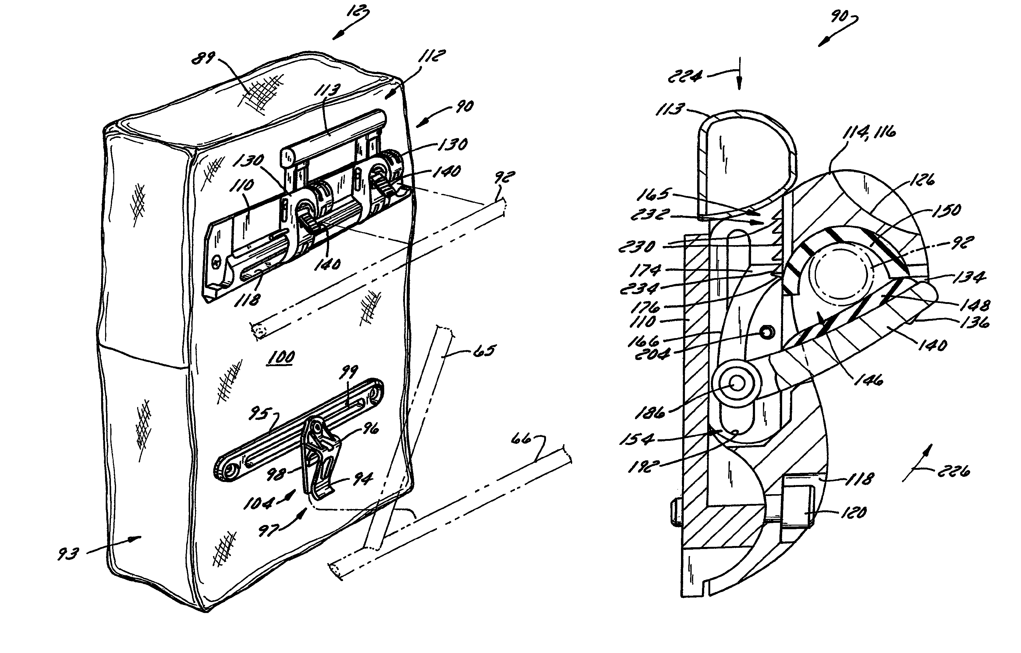
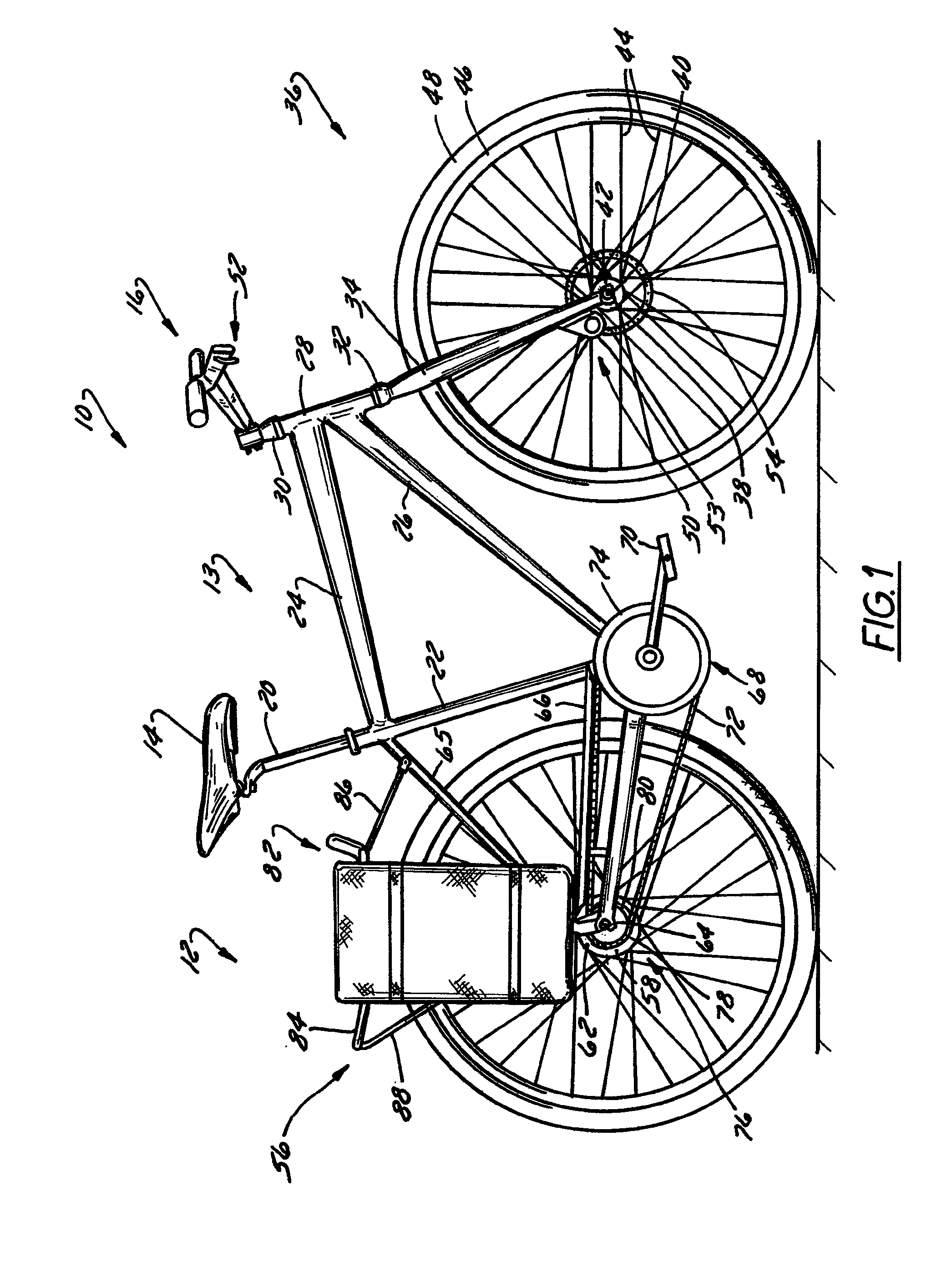
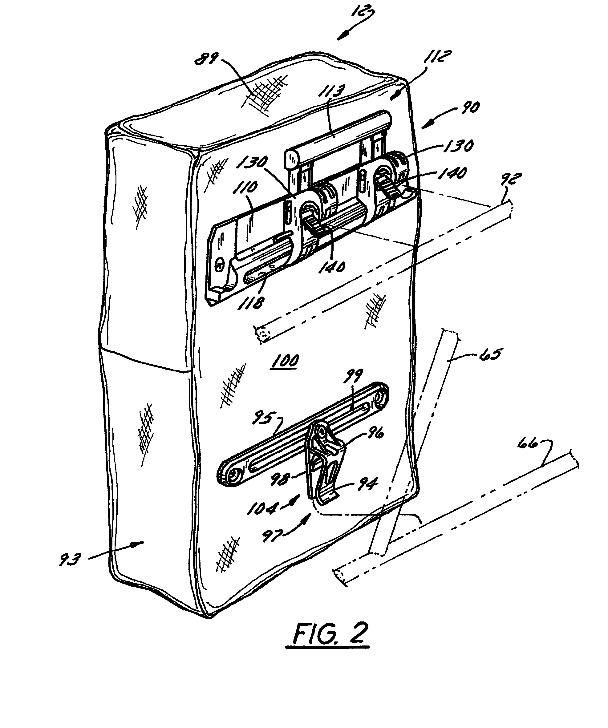
[0026]FIG. 1 shows a bicycle 10 equipped with a pannier system 12 according to the present invention. Bicycle 10 includes a frame 13 that is supported by one or more wheel assemblies 36, 56 positioned at generally opposite ends thereof. As shown, pannier system 12 is positioned outboard or rear wheel assembly 56. Understandably, pannier system 12 could be configured to cooperate with bicycle 10 so as to be positioned generally adjacent front wheel assembly 36. Furthermore, although bicycle 10 is shown to have only one pannier system 12, it is envisioned that bicycle 10 could be provided with numerous pannier systems such that a number of panniers are positioned generally adjacent front and / or rear wheel assemblies 36, 56. For those riders' desiring a greater amount of accessory storage than one pannier container provides, it is envisioned that bicycle 10 include a removable pannier system adjacent each side of front and rear wheel assemblies 36, 56 such that each wheel is generally ...


PUM


Abstract

A pannier mounting system includes a pair of hooks that are positioned at generally opposite ends of a handle and secure a pannier to a bicycle. A latch and a stop cooperate with each hook to snuggly enclose a rail in a manner that is generally independent of the cross-sectional size / shape of the rail. The latch is connected to the hook by a pivot and extends outward generally under the hook. The stop is pivotably and slidably connected to the hook and cooperates with the hook to generally fix a position of the latch. Translation of the handle toward the hooks closes and locks the latch about a rail member and translation of the handle away from the hooks unlocks the latch so that the mounting system can be removed from a rail.

Description

BACKGROUND OF THE INVENTION[0001]The present invention relates generally to bicycle accessory carriers and, more particularly, to a bicycle pannier mounting system.[0002]Interest in recreational and / or competitive cycling continues to increase. The consequence of this popularity of bicycle riding has been a growing presence of bicycle operators or riders or cyclists, of all ages, on public roads or off road trails. Further, as the recreation has grown, typical bicycle excursions or trips have lengthened in extent and, concomitantly a great variety of lighter, multi-geared and faster bicycles have entered the marketplace. Increasingly, as the utility and recreation of bicycling experiences resurgence, trips of longer durations and distances are common as is rider preference to carry several accessories with them during such trips. Increasing, riders in urban as well as nearby suburban areas have returned to bicycling as an efficient and inexpensive means to commute to and from work.[...

Claims


Application Information

Patent Timeline
Patent Type & Authority Patents(United States)
IPC IPC(8): B62J9/00
CPCB62J7/08B62J9/001B62J9/23B62J9/27
Inventor GOLUB, ERICA MARIELIAO, PO CHIN
Owner TREK BICYCLE CORPORATION
Why Eureka
Try Eureka