Protective sheath

a protective sheath and shielding technology, applied in the direction of electrical apparatus construction details, electrical apparatus casings/cabinets/drawers, instruments, etc., can solve the problems of inconvenient operation, and achieve the effect of stabilizing standing and expanding the display area

Inactive Publication Date: 2015-04-21
HSU FU YI
View PDF38 Cites 32 Cited by
  • Summary
  • Abstract
  • Description
  • Claims
  • Application Information

AI Technical Summary

Benefits of technology

[0007]The present invention is directed to a protective sheath, wherein the protective sheath is capable of protecting the display surface of the portable electronic device by using the front plate thereof, assisting the portable electronic device in stably standing on a carrying surface by using the rear plate thereof, and further inputting or expanding the display region by using the human-machine interaction (HMI) thereof.
[0025]Accordingly, the protective sheath is capable of protecting the display surface of the portable electronic device by using the front plate thereof, assisting the portable electronic device in stably standing on a carrying surface by using the rear plate thereof, and further inputting or expanding the display region by using the HMI thereof.

Problems solved by technology

However, it is quite inconvenient to operate, especially to key messages in, the unfoldable portable electronic device standing on the carrying surface since it is generally designed without a keyboard.

Method used


Image

  • Protective sheath
  • Protective sheath
  • Protective sheath

Examples


Embodiment Construction

[0028]Reference will now be made in detail to specific embodiments of the present invention. Examples of these embodiments are illustrated in the accompanying drawings. While the invention will be described in conjunction with these specific embodiments, it will be understood that it is not intended to limit the invention to these embodiments. In fact, it is intended to cover alternatives, modifications, and equivalents as may be included within the spirit and scope of the invention as defined by the appended claims. In the following description, numerous specific details are set forth in order to provide a thorough understanding of the present invention. The present invention may be practiced without some or all of these specific details. In other instances, well-known process operations are not described in detail in order not to obscure the present invention.

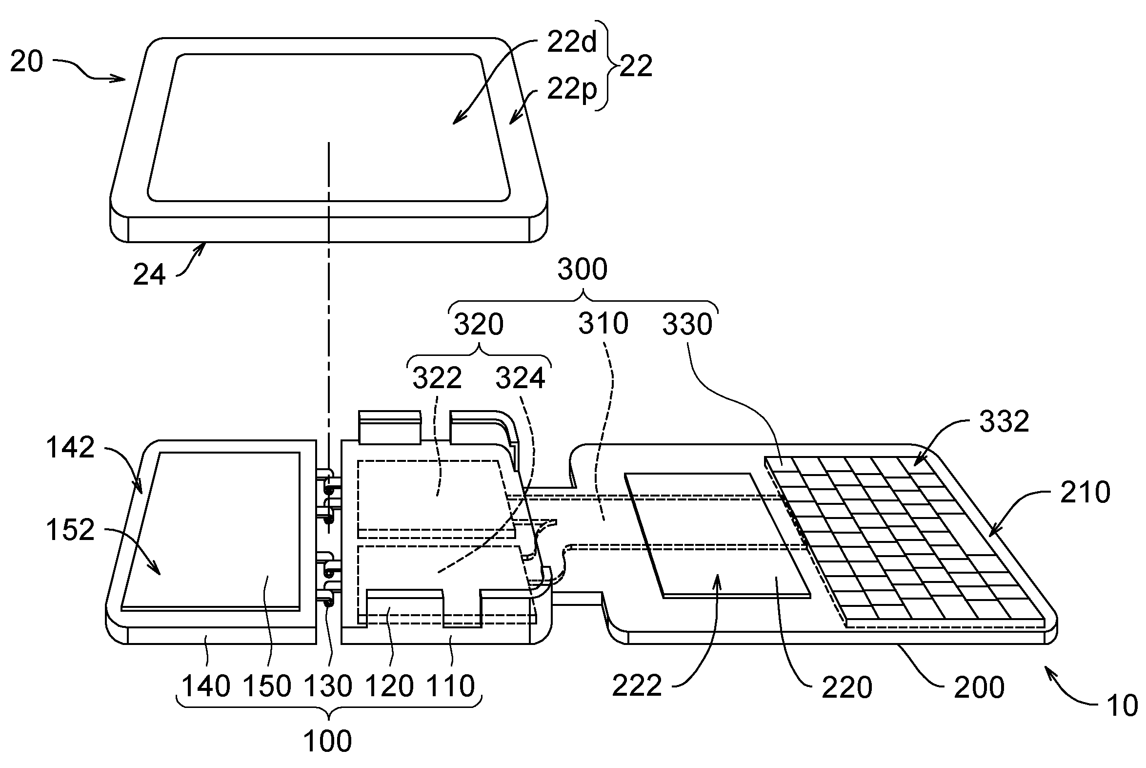
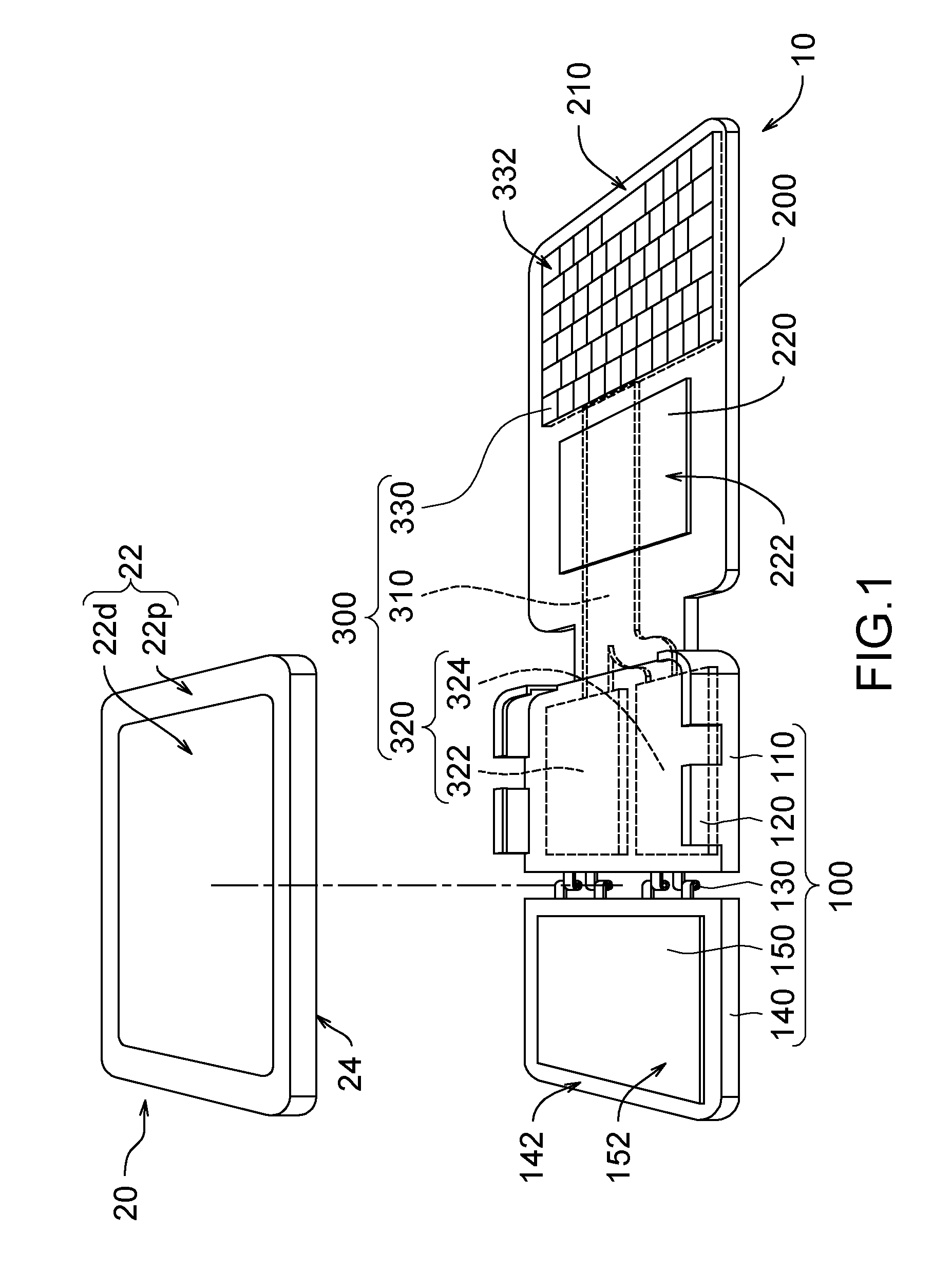
[0029]FIG. 1 illustrates a structural schematic perspective view of a protective sheath disassembled from a portable electr...


PUM


Abstract

A protective sheath comprises a rear plate, a front plate and a wireless HMI device comprising a main portion embedded inside the rear plate, a human-machine interface embedded inside the front plate and a soft flat cable electrically connecting there-between. The front plate comprises a first folding plate, a holding component for holding a portable electronic device on the first folding plate, a position limiting hinge, and a second folding plate pivoted to the first folding plate via the position limiting hinge. Hence, the first and the second folding plates can cover a rear surface of the portable electronic device together by being relatively unfolded, and are maintained at a presetting pivoting angle by the position limiting hinge after being relatively folded. The front plate can be folded relative to the first folding plate to cover a display surface of the portable electronic device.

Description

CROSS-REFERENCE TO RELATED APPLICATIONS[0001]This application claims priority from Taiwan Patent Application No. 101219649, filed 2012 Oct. 11, the contents of which are hereby incorporated by reference in their entirety for all purposes.FIELD OF THE INVENTION[0002]The present invention generally relates to a protective sheath, and more particularly to a protective sheath for a portable electronic device.DESCRIPTION OF THE RELATED ART[0003]With the development of technology, various portable electronic devices, such as a multimedia player (MP3, MP4 and so on), a cell phone, a personal digital assistant (PDA), a smart phone, a hand-held game console, an electronic book (E-book), a tablet personal computer (tablet PC), a netbook, a notebook and so on, have become an integral part of modern life to many people. To compare with the traditional desktop personal computer (desktop PC), a main advantage of the portable electronic device is easy to get carried. Therefore, in recent years, we...

Claims


Application Information

Patent Timeline
Patent Type & Authority Patents(United States)
IPC IPC(8): H05K5/00G06F1/16B65D85/00H05K7/00H05K7/14
CPCH05K7/1401G06F1/1632G06F1/1654G06F1/1669
Inventor HSU, FU-YI
Owner HSU FU YI
Why Eureka
Try Eureka