Carrying case with locking latch mechanism

a latch mechanism and carrying case technology, applied in the field of carrying cases, can solve the problems of easy loss of keys, difficulty in conveying the combination of locks to a group,

Active Publication Date: 2012-10-30
GRENIER JEAN PIERRE +2
View PDF31 Cites 87 Cited by
  • Summary
  • Abstract
  • Description
  • Claims
  • Application Information

AI Technical Summary

Benefits of technology

[0007]The purpose of the latch release is to prevent inadvertent pivotal motion of the latch body, which, in turn, would allow the latch locking element to disengage the top case shell. As described in detail below, the latch release is movable between a locked position and a release position. In the locked position, the latch release engages the front wall of the bottom case shell and prevents pivotal motion of the latch body. In turn, the latch locking element is maintained in position against the seat of the top case shell thus retaining the case in the closed position. Upon movement of the latch release to the release position, the latch body is free to pivot thus allowing the latch locking element to disengage from the top case shell.

Problems solved by technology

If a carrying case may be used by several people, it is difficult to convey the combination of a lock to a group, whose members may change, and keys are easily lost.
Further, security requirements at airports do not permit locking of cases or luggage, and such cases may be inadvertently opened by baggage handlers.

Method used


Image

  • Carrying case with locking latch mechanism
  • Carrying case with locking latch mechanism
  • Carrying case with locking latch mechanism

Examples


Embodiment Construction

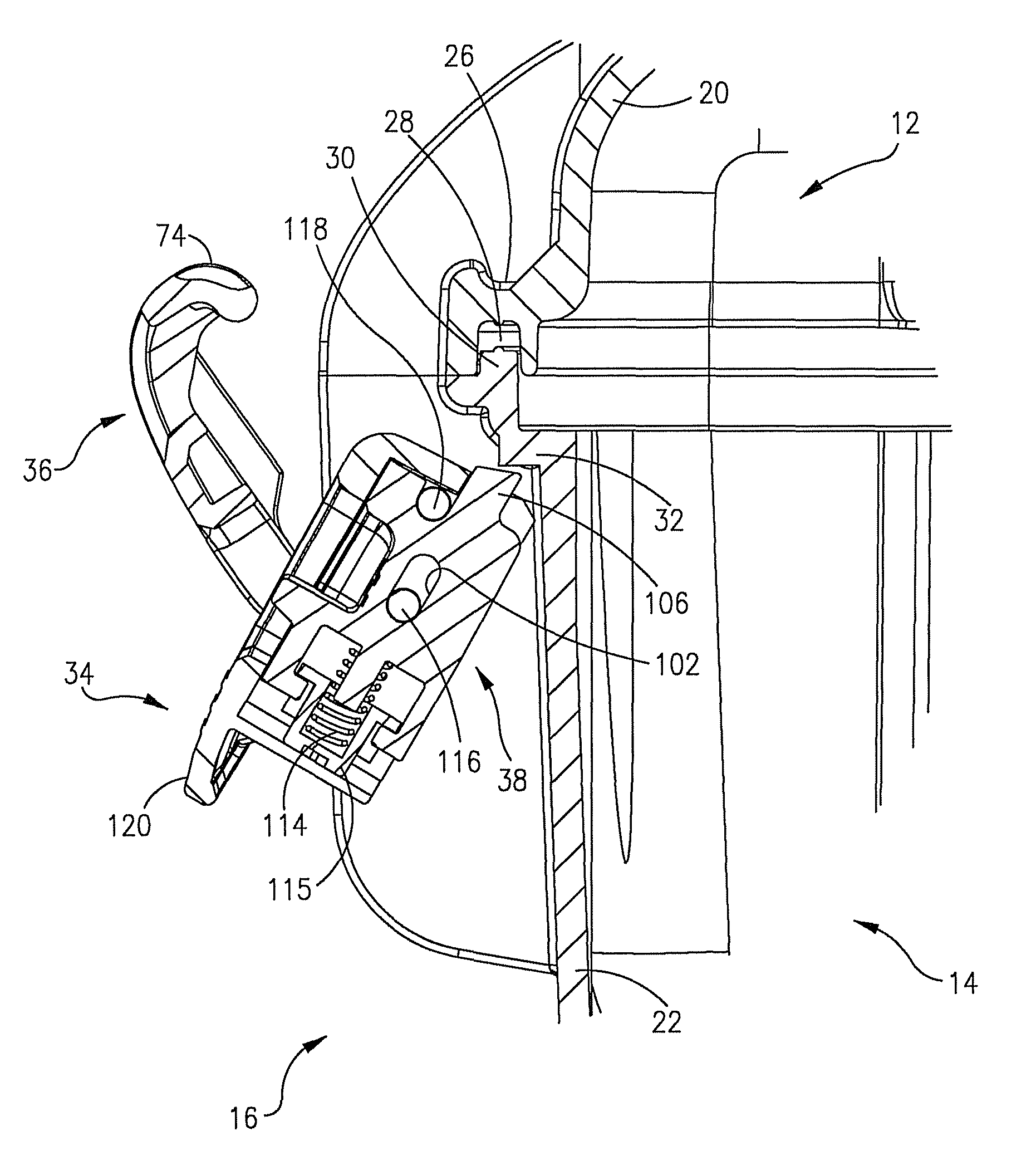
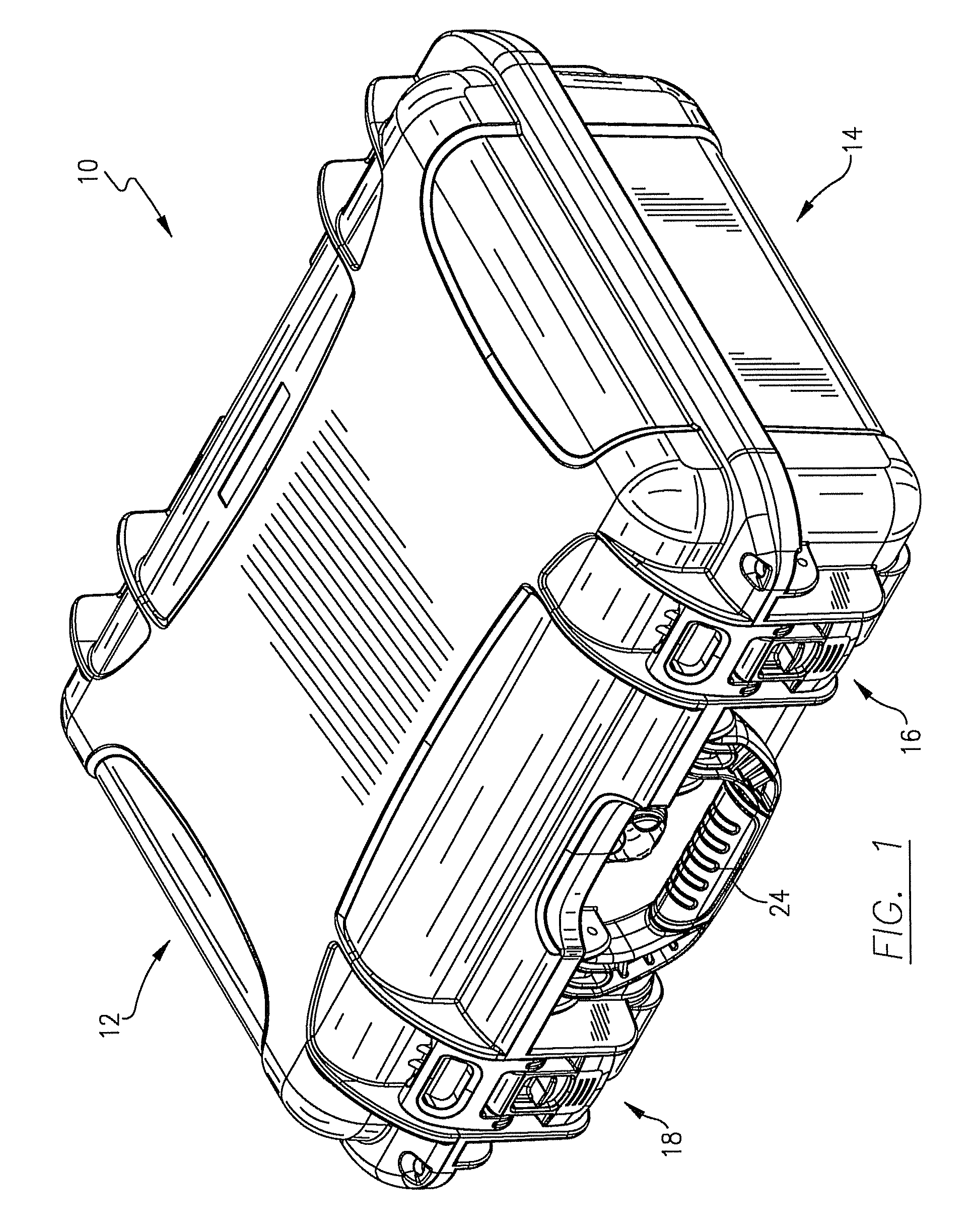
[0024]Referring initially to FIGS. 1 and 6, a carrying case 10 is depicted having a top case shell 12 pivotally connected to a bottom case shell 14. Two latch mechanisms 16 and 18 are located along the front wall 20 of shell 12 and front wall 22 of shell 14 on either side of a handle 24. As best shown in FIG. 6, the front wall 20 of top case shell 12 is formed with a seat 26 and a downwardly facing slot 28 which receives the upper edge 30 of the front wall 22 of bottom case shell 14 when the case 10 is closed. The front wall 22 of the bottom case shell 14 is formed with a ledge 32, for purposes to become apparent below. Except as noted above, the detailed construction of the case 10 forms no part of this invention and is not described herein. Additionally, for purposes of the present discussion, the terms “top,”“bottom,”“upper,”“lower,”“downwardly,”“upwardly” and the like refer to the vertical orientation of the case as it is depicted in the Figs.

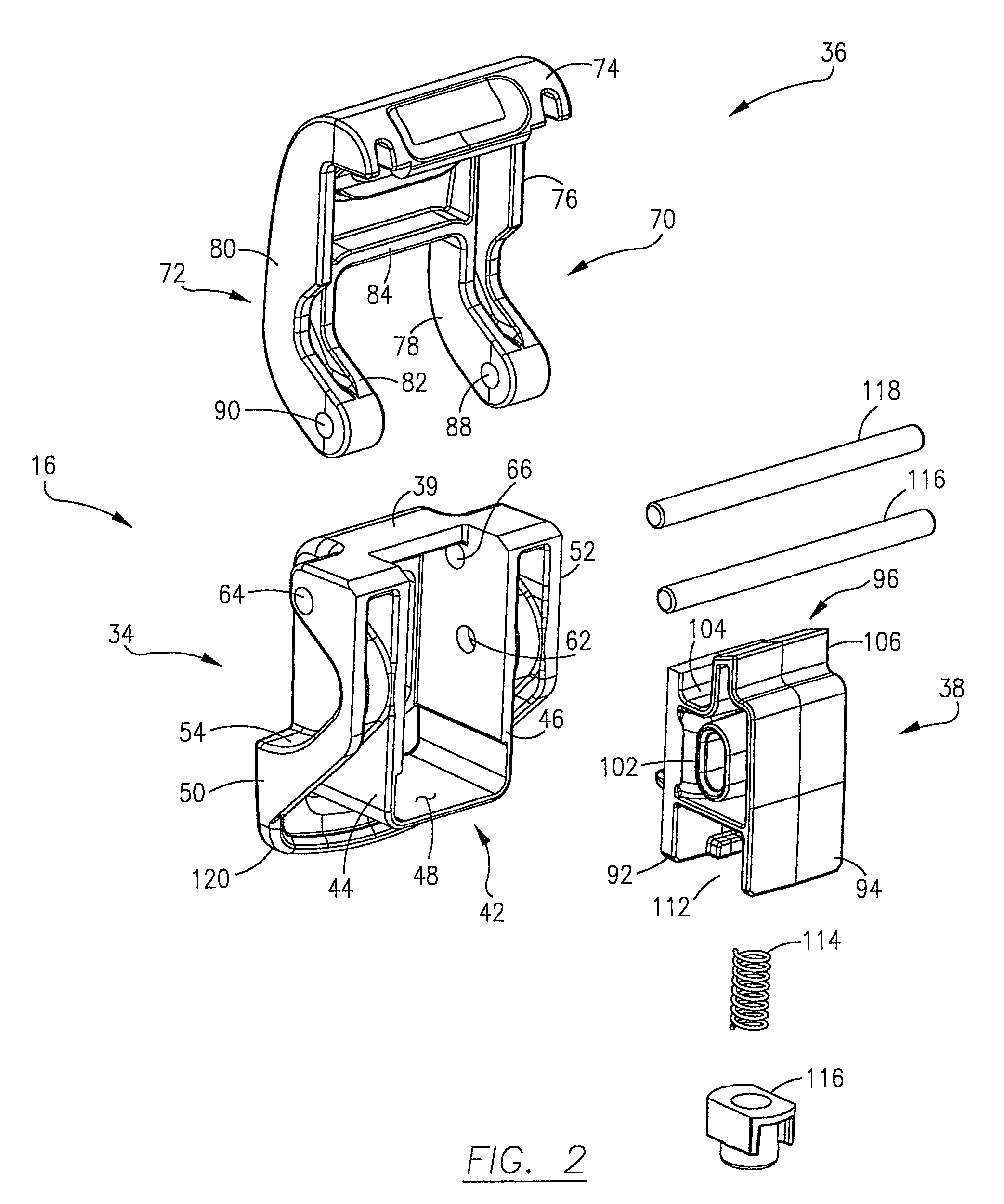
[0025]With reference to FIGS. 2-5, t...


PUM


Abstract

A carrying case includes a top case shell hinged to a bottom case shell which may be maintained in a closed position by a double throw, triple action latch mechanism comprising a latch body pivotally mounted to the bottom case shell, a latch locking element pivotally mounted to the latch body and a latch release coupled to the latch body. With the case in the closed position, the latch locking element engages a seat formed in the top case shell and clamps the two shells together. After moving the latch release to a release position, the latch body may be pivoted relative to the bottom case shell to permit disengagement of the latch locking mechanism from the top shell allowing the case to be opened.

Description

RELATED APPLICATION[0001]This application is a continuation-in-part application of U.S. patent application Ser. No. 11 / 762,497 filed Jun. 13, 2007, for all commonly disclosed subject matter. U.S. application Ser. No. 11 / 762,497 is expressly incorporated herein by reference in its entirety to form part of the present disclosure.FIELD OF THE INVENTION[0002]This invention relates to carrying cases, and, more particularly, to carrying cases with a double throw, triple action latch mechanism having a locking feature which substantially prevents inadvertent opening of the latch mechanism.BACKGROUND OF THE INVENTION[0003]Carrying cases typically include a top case shell and a bottom case shell pivotally connected by a hinge. The two shells are maintained in a closed position by one or more latch mechanisms located along the front and / or the sides of the case. A variety of latch mechanisms have been employed in the past, such as single throw and double throw latches, some of which may be lo...

Claims


Application Information

Patent Timeline
Patent Type & Authority Patents(United States)
IPC IPC(8): B65D45/16
CPCA45C13/1084E05C19/14E05B65/52A45C2005/037E05B13/10Y10T70/5058Y10T292/0917
Inventor GRENIER, JEAN-PIERRECOLEY, BENJAMINHAWKINS, GARY
Owner GRENIER JEAN PIERRE
Why Eureka
Try Eureka