Rotating fluid nozzle for tube cleaning system

a technology of rotating fluid nozzle and cleaning system, which is applied in the direction of cleaning process and apparatus, cleaning using liquids, chemistry apparatus and processes, etc., and can solve problems such as the counter-force of shaft forces

Active Publication Date: 2012-10-30
NEW LANTAO BUS
View PDF62 Cites 22 Cited by
  • Summary
  • Abstract
  • Description
  • Claims
  • Application Information

AI Technical Summary

Problems solved by technology

One challenge with such high pressure jet nozzles is the countering of the forces on the shaft from the water.

Method used


Image

  • Rotating fluid nozzle for tube cleaning system
  • Rotating fluid nozzle for tube cleaning system

Examples


Embodiment Construction

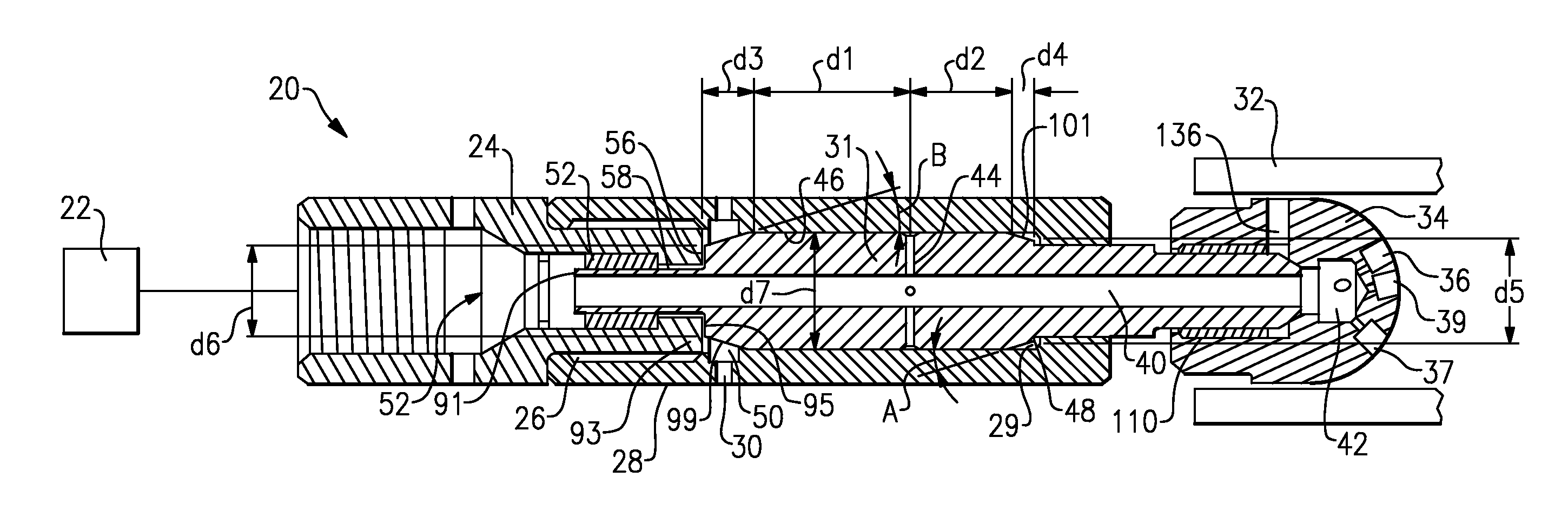
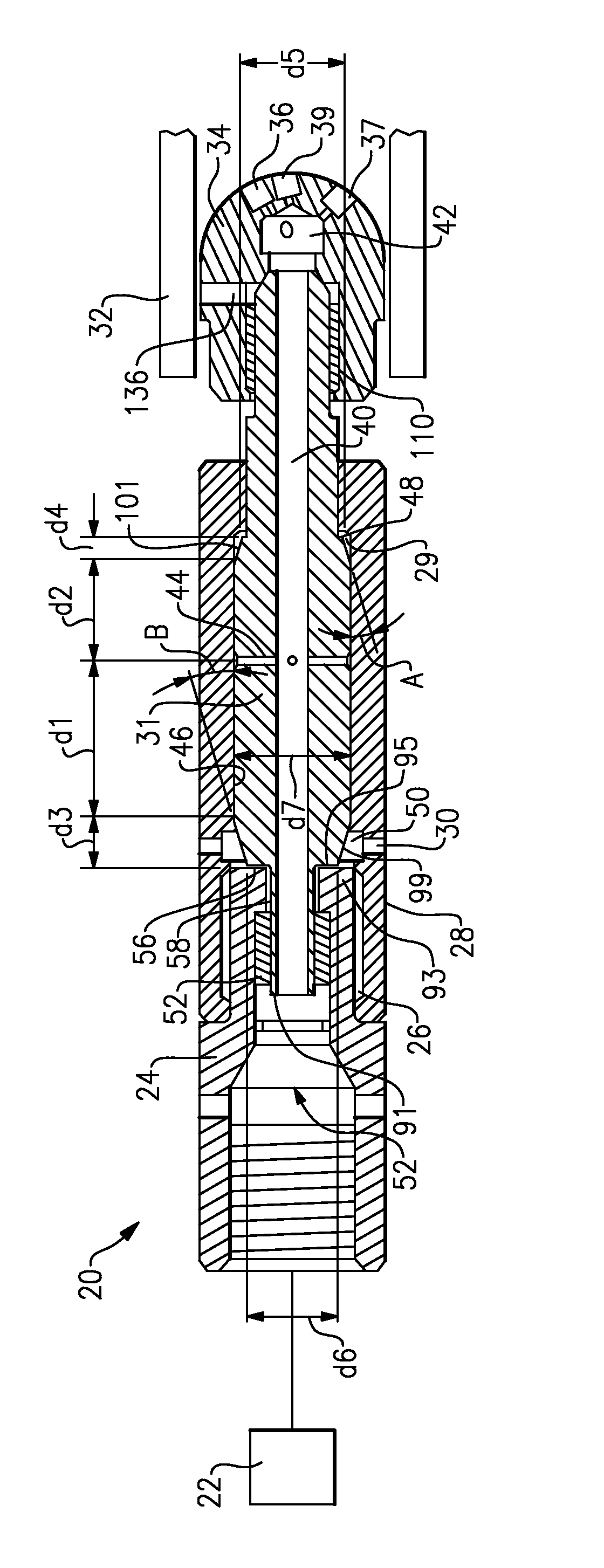
[0007]FIG. 1 shows a rotating nozzle head 20 for being connected to a source of high pressure fluid 22. One such source may be that disclosed in co-pending patent application Ser. No. 12 / 475,912, filed on Jun. 1, 2009, entitled “EASY CHANGE TUBE CLEANING SYSTEM.”

[0008]However, other ways of providing pressurized water to the nozzle would come within the scope of this invention.

[0009]A first housing 24 includes threads to be secured to a component for delivering the water. A second fixed housing 28 is connected through a thread connection 26 to the first housing 24. The second housing 28 extends forwardly to a ledge 29. The ledge 29 extends radially inwardly relative to a central axis of the system 20 and provides a pressure fluid chamber 48 at an end of a rotating shaft 31.

[0010]The rotating shaft 31 has an inlet end 91, which has a relatively small outer diameter, and is received within a bushing. Bushing 52 minimizes leakage between the outer periphery of the portion 91 and the in...


PUM


Abstract

A fluid nozzle for use in a high pressure water jetting system includes a housing to be fixed to a source of high pressure water. The housing receives a rotating member and an inner peripheral bore. The rotating member includes a shaft received within the housing, and a nozzle extending outwardly of the housing, the nozzle having openings extending along a direction having a component both forwardly along an axis of rotation of the shaft and the nozzle, and radially outwardly relative to the central axis. A central passage within the shaft communicates high pressure fluid to the nozzle. The shaft includes leakage paths to provide leakage fluid from the central passage to an interface between an outer peripheral wall of the shaft and an inner peripheral wall of the bore in the housing. The leakage paths communicate fluid to a forward fluid pressure chamber, and to a rearward fluid pressure chamber. A pressure loss to the rearward fluid pressure chamber is greater than a pressure drop at the forward pressure chamber.

Description

BACKGROUND OF THE INVENTION[0001]This application relates to a rotating nozzle for use in a cleaning system such as may be utilized to clean the interior of tubes, and wherein a pressure drop differential between an inlet side and an outlet side of a rotating shaft is utilized to provide a fluid thrust to properly support the shaft.[0002]Systems utilized to clean the interior of tubes, or other small hollow parts, with the use of a high pressure water jets are known. Typically, a rotating fluid nozzle is inserted into the interior of a tube, and moved along that interior. A source of high pressure water is connected to the nozzle and jets outwardly of nozzle openings at a forward end of the nozzle. The jetting fluid impacts against an interior surface, cleaning the tube.[0003]One challenge with such high pressure jet nozzles is the countering of the forces on the shaft from the water.SUMMARY OF THE INVENTION[0004]A fluid nozzle for use in a high pressure water jetting system include...

Claims


Application Information

Patent Timeline
Patent Type & Authority Patents(United States)
IPC IPC(8): B08B9/093
CPCB05B3/06B05B13/0636B08B9/0433B05B3/002
Inventor WOJCIECHOWSKI, III, DONALD ANTHONYHERHOLD, MATTHEW O.
Owner NEW LANTAO BUS
Why Eureka
Try Eureka