
Fish strike indicator

a technology of indicator and fish, which is applied in the direction of rods, other angling devices, animal husbandry, etc., can solve the problems of increasing difficulty for anglers to watch difficulty in seeing bobbers in ice fishing holes, and constant monitoring of the tip of their poles, so as to minimize the flexural characteristics of the fishing rod, minimize the obtrusiveness of the user, and easy to use

Active Publication Date: 2012-11-06
CARIGNAN LAWRENCE WILLIAM +1
View PDF22 Cites 3 Cited by
  • Summary
  • Abstract
  • Description
  • Claims
  • Application Information

AI Technical Summary

Benefits of technology

[0022]According to one advantage of the present invention, the fish strike indicator is designed for use with poles of various sizes. This is accomplished in a preferred embodiment by utilizing a compressible material within the channel of the main body.
[0023]According to another advantage of the present invention, the fish strike indicator has a rod lock that is fixed about the fishing rod at a single location to minimize any changes in the flexural characteristics of the fishing rod. The rod lock is easy to use. The fish strike indicator can be stored on the rod without any interference to the operation of the rod when the angler chooses to not use the fish strike indicator.
[0024]According to a further advantage of the present invention, the fish strike indicator has a trigger with a kick-out post to release a signal from a ready position to a deployed position. Accordingly, the movement of the trigger directly causes deployment of the indicator without any intermediate parts.
[0025]According to a still further advantage of the present invention, the fish strike indicator has a trigger that is flush with the main body during a storage position so as to minimize obtrusiveness to the user.
[0026]According to a still further advantage yet of the present invention, the fish strike indicator tension assembly can lock the indicator in a storage position that is unobtrusive to the angler.
[0027]According to a still further advantage yet of the present invention, the fish strike indicator trigger fully releases the line after a fish strike to enable normal operation of the fishing apparatus.

Problems solved by technology

The disadvantage of this method is that it is very difficult to see a bobber in the ice fishing hole if the angler is more than about fifteen feet away from it due to the geometry of the line of site into the fishing hole.
One main drawback with this method is that the angler must constantly watch the tip of their pole for any movement indicative of a fish strike.
Visibility is also the big drawback to this method due to the fact that the pole becomes increasingly more difficult to see the further the angler is from it.
A major disadvantage to both the bobber and the “dead stick” methods is that they only notify an angler during a fish strike event.
The angler may then unknowingly be missing the bait on the end of their line.
As the angler pulls the fish in through the ice hole, the excess line is dropped onto the ice, frequently becoming tangled.
While each of these products may work well for their intended purposes, each is not without drawbacks.
One drawback of this invention is that it does not appear to release the line after a strike.
This can be problematic, since fishing poles do not have a uniform dimension.
Also, having the device connect to the pole at two locations can interfere with the engineered flexural characteristics of the fishing pole.
This product appears to connect to the handle, which some anglers find objectionable.
None of these devices show a fish strike indicator that is designed for use with poles of various sizes.
None of these devices show a fish strike indicator that has a rod lock that is fixed about the fishing rod at a single location on the rod to minimize any changes in the flexural characteristics of the fishing rod.
None of these devices show a trigger with a kick-out post to release a signal from a ready position to a deployed position.
None of these devices show a trigger tensioner that can set the sensitivity of the trigger and also lock the fish strike indicator in the storage position.

Method used


Image

  • Fish strike indicator
  • Fish strike indicator
  • Fish strike indicator

Examples


Embodiment Construction

[0044]While the invention will be described in connection with one or more preferred embodiments, it will be understood that it is not intended to limit the invention to those embodiments. On the contrary, it is intended to cover all alternatives, modifications and equivalents as may be included within the spirit and scope of the invention as defined by the appended claims.

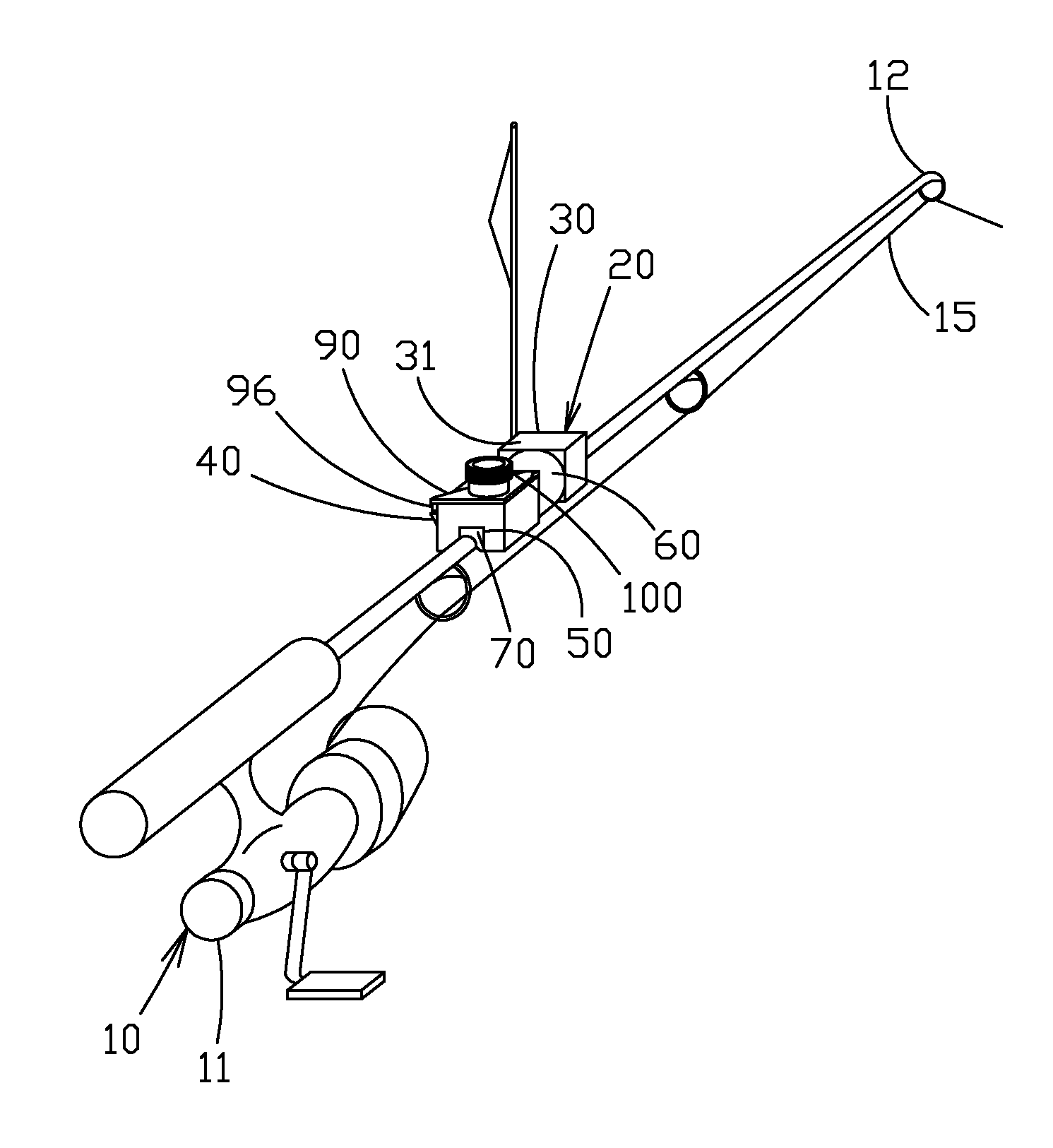
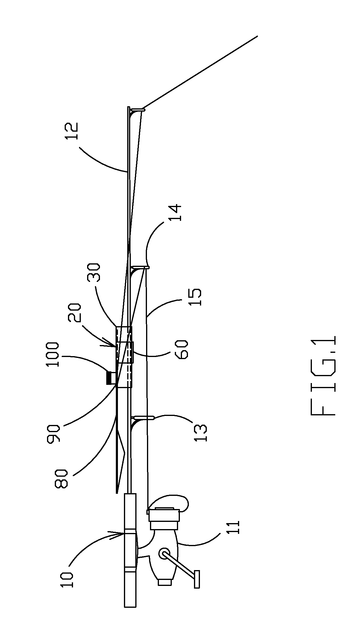
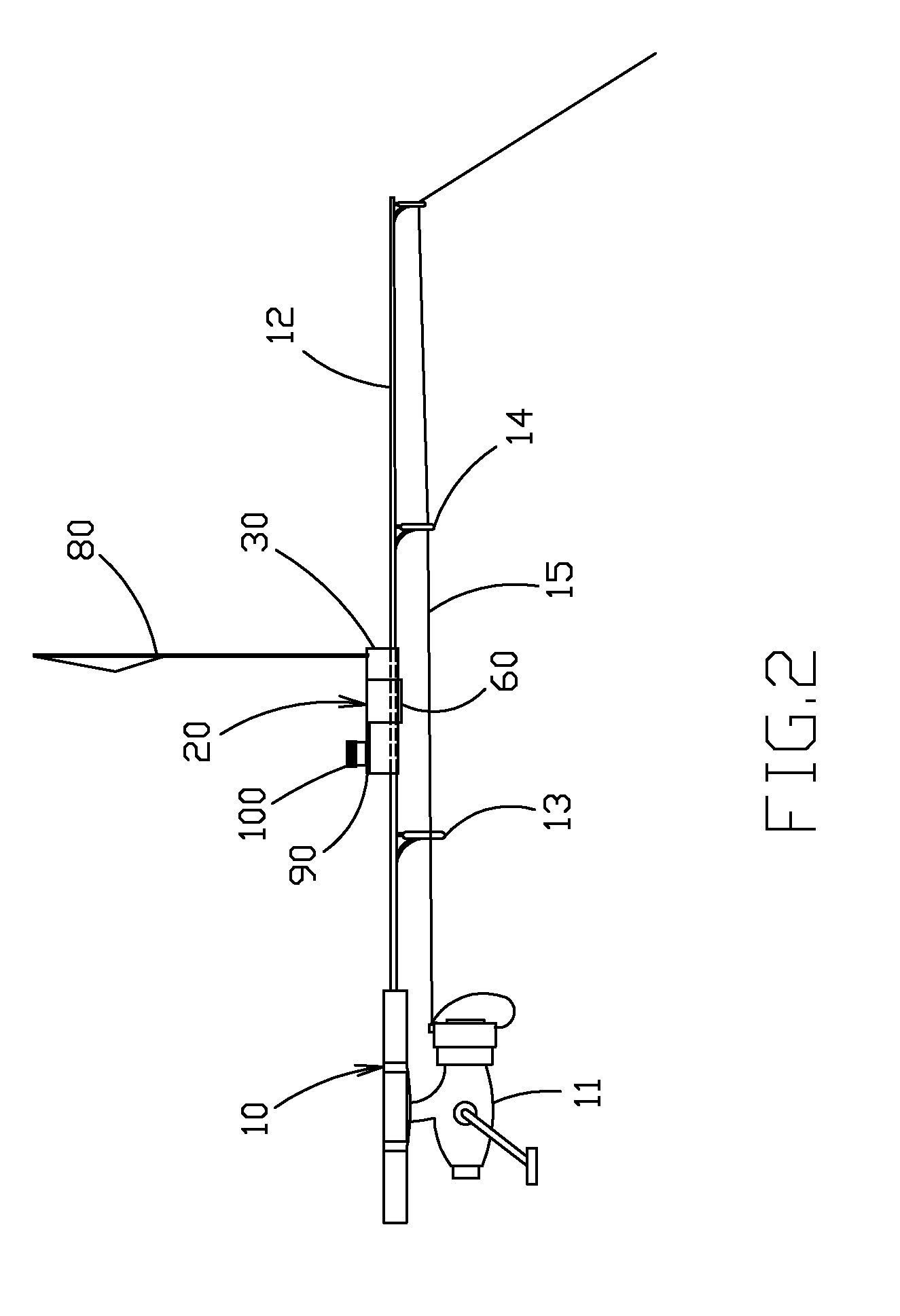
[0045]The present invention can be used with a conventional fishing apparatus 10. The fishing apparatus can have a reel 11 and a rod 12. Eyelets 13 and 14 are provided along the length of the rod. The rod has a longitudinal axis. A selected amount and type of line 15 can be placed through the eyelets during use. The exact dimensions of the fishing apparatus are not important, as the present invention as described below accommodates rods of various sizes.

[0046]Turning now to the present invention, it is seen that a preferred embodiment of an indicator 20 is provided in FIGS. 1-14. The indicator 20 generally compris...


PUM


Abstract

A fish strike signal that can selectively be placed in a storage position, a ready position or a deployed position. The signal has a main body with a storage ledge, a retainer and a pocket. A trigger is provided having a notch for engaging a segment of fishing line and having a kick-out post for deploying a signal. The kick-out post can be held with a pocket in the ready position. Rotation of the trigger caused by a strike forces the post from the pocket and causes the wire of the signal to clear a retainer on the side of the main body. A tension assembly is provided for adjusting the amount of force that is required to rotate the trigger. The post and a ledge holds the signal in place and the tensioner can be used to lock the signal in the storage position.

Description

[0001]This utility patent application claims priority on and the benefit of provisional application 61 / 120,434 filed Dec. 6, 2008, the entire contents of which are hereby incorporated herein by reference.BACKGROUND OF THE INVENTION[0002]1. Field of the Invention[0003]The present invention relates to a fish strike indicator, and in particular to a fish strike indicator that is non-obtrusive to the user, that is adjustable and that does not interfere with operation of the fishing rod and reel after the indicator is deployed.[0004]2. Description of the Related Art[0005]Fishing, and in particular ice fishing, is an extremely popular sport. There are numerous methods and devices used by the ice fishers in this sport.[0006]One method employs the use a slip bobber to indicate a strike. The disadvantage of this method is that it is very difficult to see a bobber in the ice fishing hole if the angler is more than about fifteen feet away from it due to the geometry of the line of site into th...

Claims


Application Information

Patent Timeline
Patent Type & Authority Patents(United States)
IPC IPC(8): A01K97/12
CPCA01K97/12
Inventor CARIGNAN, LAWRENCE WILLIAMCARIGNAN, DARIN ALLAN
Owner CARIGNAN LAWRENCE WILLIAM
Learn More