Bracket

a technology of brackets and supports, applied in the field of brackets, can solve problems such as complex rotating mechanisms of typical structures

Inactive Publication Date: 2012-11-27
FU TAI HUA IND SHENZHEN +1
View PDF13 Cites 65 Cited by
  • Summary
  • Abstract
  • Description
  • Claims
  • Application Information

AI Technical Summary

Problems solved by technology

However, the typical r...

Method used


Image

  • Bracket
  • Bracket
  • Bracket

Examples


Embodiment Construction

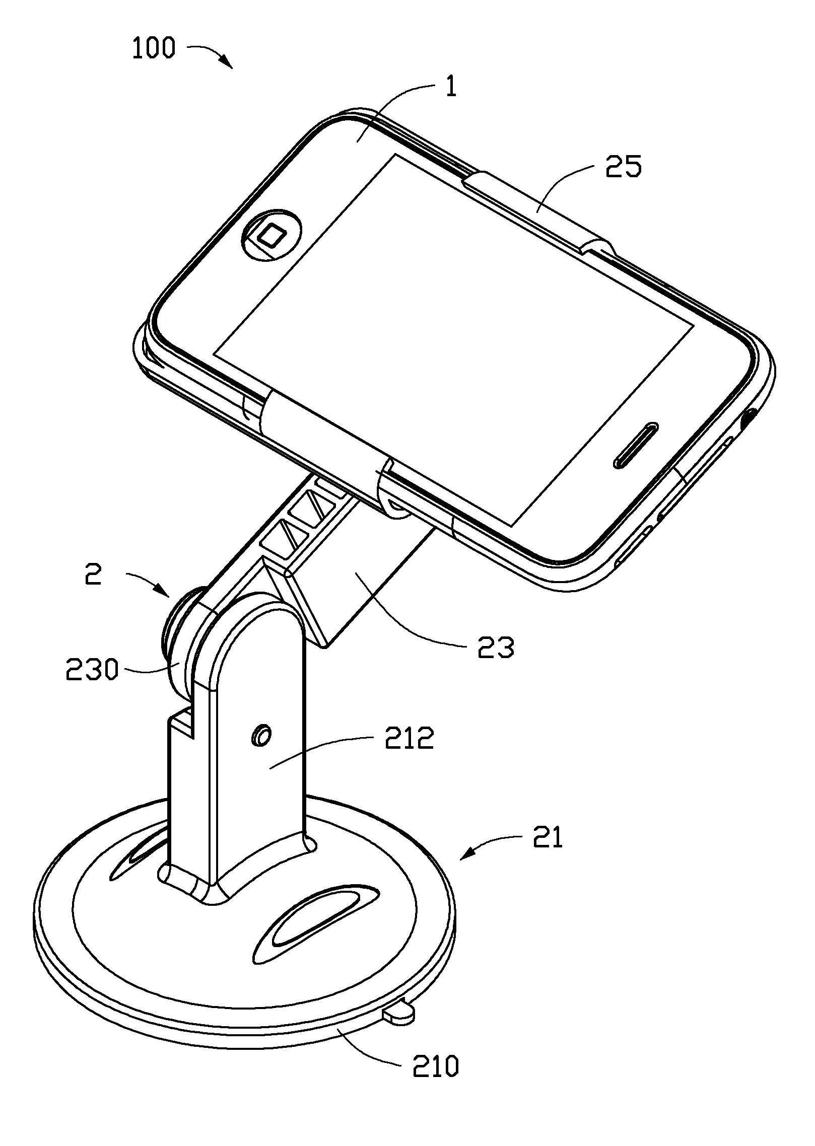
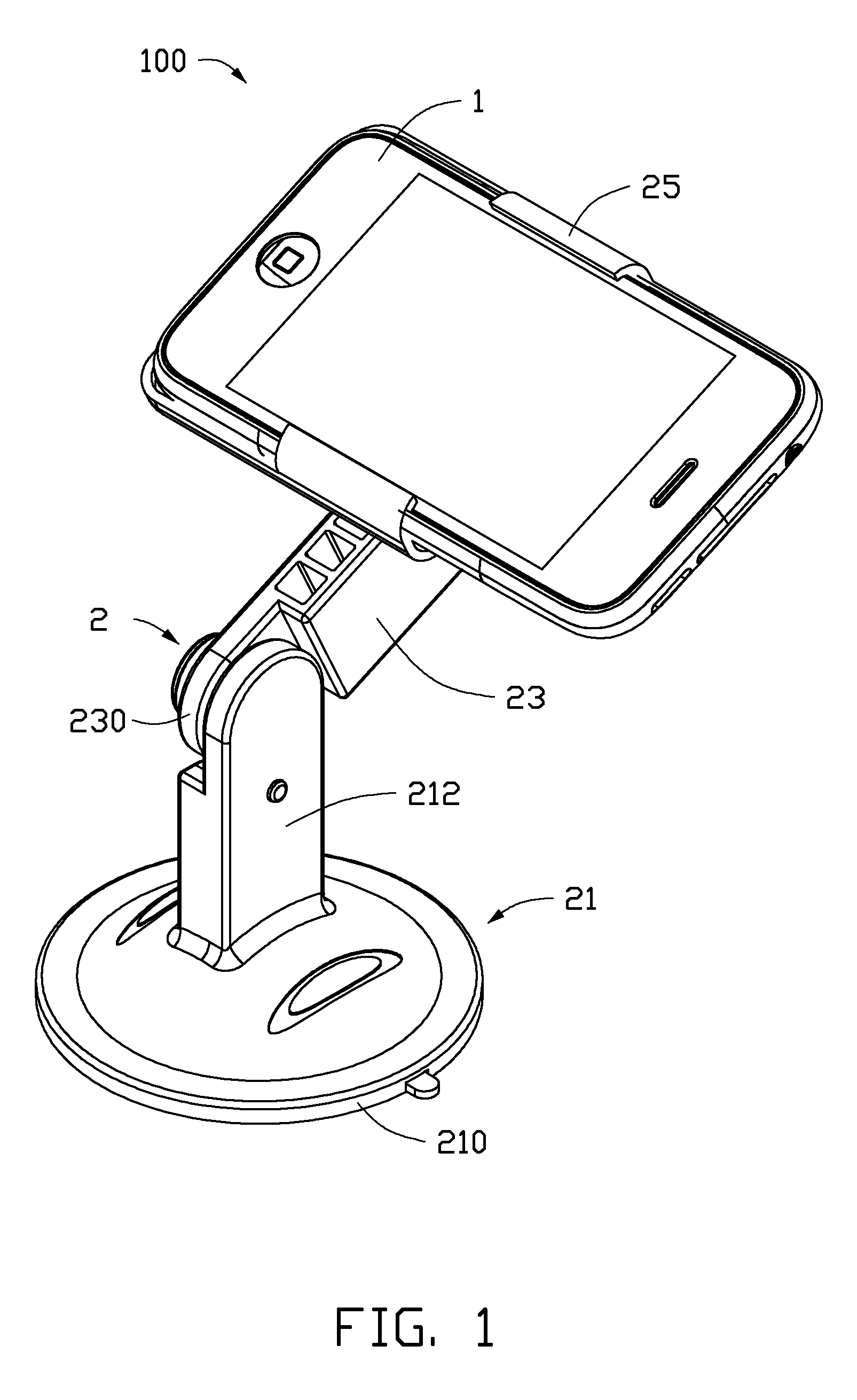
[0012]FIG. 1 shows an embodiment of an electronic apparatus 100 including an electronic device 1, and a bracket 2 for mounting the electronic device 1 to a flat surface, such as a desktop.

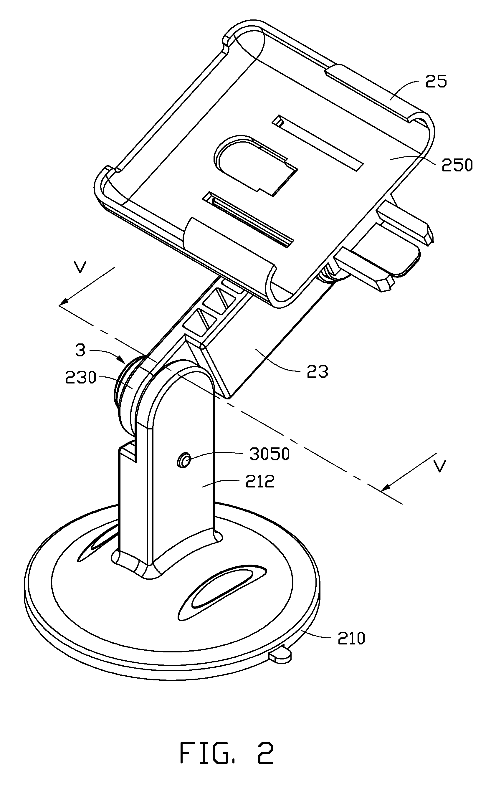
[0013]Referring also to FIGS. 2-4, the bracket 2 includes a receiving part 25, a base 21, a rotating arm 23, and a locking device 3. The electronic device 1 is removably received in the receiving part 25. The base 21 is removably attached to the flat surface to secure the electronic device 1 to the flat surface. One end of the rotating arm 23 is rotatably connected to the base 21, the other end of the rotating arm 23 is rotatably connected to the receiving part 25. The locking device 3 is connected between the base 21 and the rotating arm 23 to prevent the rotating arm 23 from rotating with respect to the base 21.

[0014]The receiving part 25 defines an opening 250 in which the electronic device 1 may be received, and a clamping member (not label) to secure the electronic device 1 to the bracket 2. T...


PUM


Abstract

A bracket for supporting an electronic device includes a receiving part, a rotating arm, a base, and a locking device. Two opposite ends of the rotating arm are connected to the electronic device and the base. The locking device includes a locking mechanism positioned on the rotating arm, and a locked part positioned on the base. The locking mechanism includes a locking member, an elastic member, and an operating member. The locked part defines a locked position and an unlocked position, the locking member is capable of moving from the locked position to the unlocked position, the elastic member provides an elastic force to keep the locking member in the locked position so that the rotating arm stops moving, the operating member is operable to enable the locking member to overcome the elastic force to move to the unlocked position so that the rotating arm is capable of rotating.

Description

BACKGROUND[0001]1. Technical Field[0002]The present disclosure relates to brackets, and particularly to a bracket for use in mounting an electronic device to a flat surface.[0003]2. Description of Related Art[0004]A tablet computer can be mounted to a desk by a bracket for hands free viewing. The bracket has a rotating mechanism for rotating through an angle for optimum viewing of the screen of the tablet computer. However, the typical rotating mechanism is complex.[0005]Therefore, there is room for improvement within the art.BRIEF DESCRIPTION OF THE DRAWINGS[0006]Many aspects of the embodiments can be better understood with reference to the following drawings. The components in the drawings are not necessarily drawn to scale, the emphasis instead being placed upon clearly illustrating the principles of the present embodiments. Moreover, in the drawings, like reference numerals designate corresponding parts throughout the several views.[0007]FIG. 1 is an isometric view of an electro...

Claims


Application Information

Patent Timeline
IPC IPC(8): A45D19/04F16M11/02F16M13/00A47J47/16E04G3/00G03B17/00
CPCF16M11/041F16M11/10F16M11/2021F16M13/00F16M13/022F16M2200/024
Inventor ZHOU, CONG-BING
Owner FU TAI HUA IND SHENZHEN
Why Eureka
Try Eureka