
Solar umbrella clip light

Inactive Publication Date: 2012-11-27
CHIEN LUEN INDS
View PDF20 Cites 6 Cited by
  • Summary
  • Abstract
  • Description
  • Claims
  • Application Information

AI Technical Summary

Benefits of technology

[0011]A fourth objective of the present invention is to provide illumination apparatus, devices and methods of attaching lights to outdoor umbrellas, tree branches, porches, balconies, gazebos, and the like, that are portable and easily attachable and detachable.
[0012]A fifth objective of the present invention is to provide illumination apparatus, devices and methods of attaching lights to outdoor umbrellas, tree branches, porches, balconies, gazebos, and the like, that is easily attachable and detachable.
[0013]A sixth objective of the present invention is to provide illumination apparatus, devices and methods of attaching lights to outdoor umbrellas, tree branches, porches, balconies, gazebos, and the like, where the lights can be adjustably aimed.

Problems solved by technology

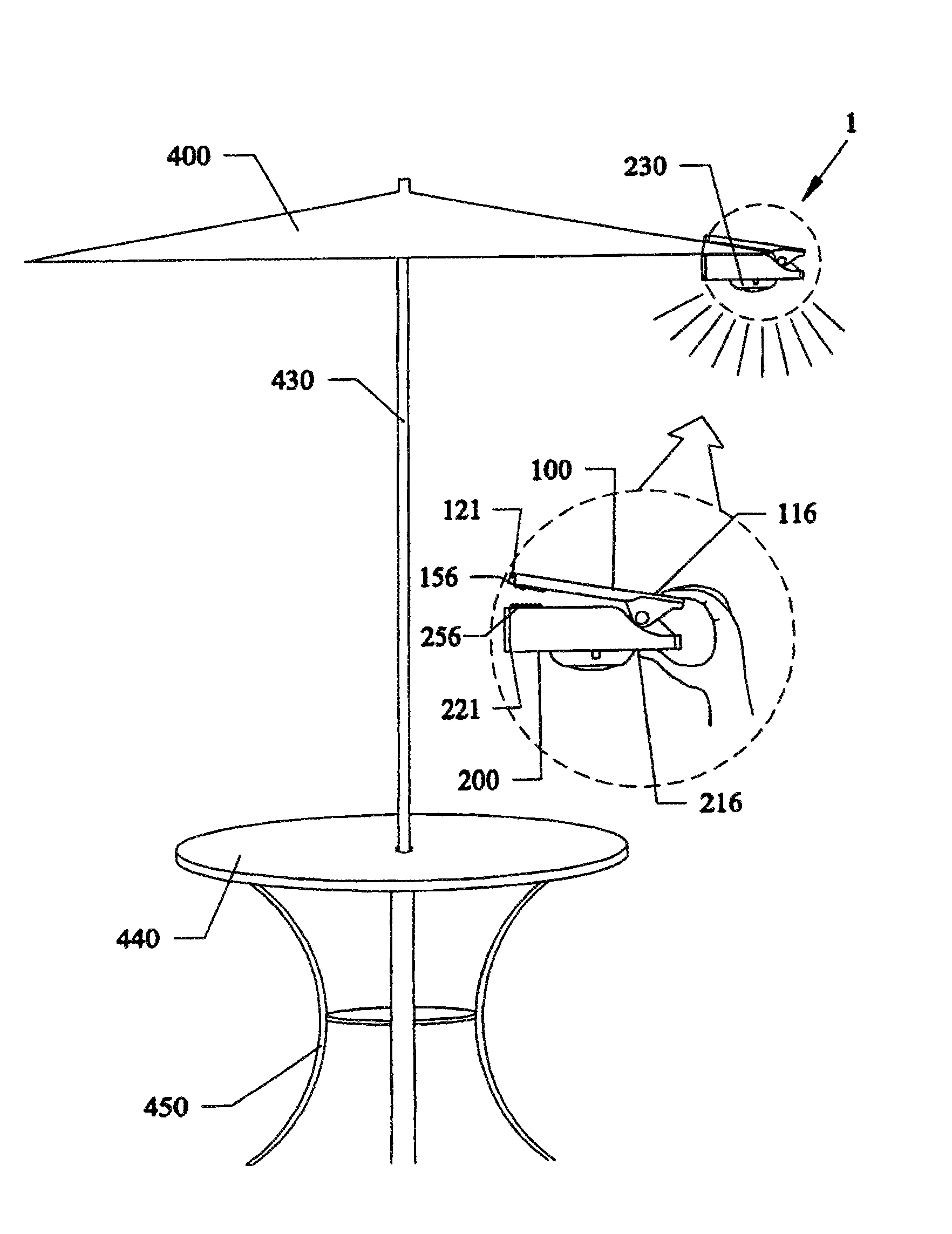
Outdoor umbrellas, such as table umbrellas, beach umbrellas and the like, are popular for daytime activities, but can create shadows underneath that take away from their productive use.
Furthermore, large table umbrellas, and beach umbrellas are often left in up positions after dark, which makes the space underneath difficult to illuminate.
Popular electrically powered lights such as those formed from stringing electrical lines to power small lights and the like, can also be difficult to use, and are not practical in outdoor environments that have no power supplies in close proximity to the umbrellas.
However, the Sohn publication requires the use of batteries which would not last for long time periods and would need replacement over time.
Additionally, the lights point forward, and would not be useful for lighting an area beneath an umbrella.
Still furthermore, the light sources referenced above are fixed, and cannot be moved to adjust the light beam once the lights are installed in place.

Method used


Image

  • Solar umbrella clip light
  • Solar umbrella clip light
  • Solar umbrella clip light

Examples


Embodiment Construction

[0041]Before explaining the disclosed embodiments of the present invention in detail it is to be understood that the invention is not limited in its applications to the details of the particular arrangements shown since the invention is capable of other embodiments. Also, the terminology used herein is for the purpose of description and not of limitation.

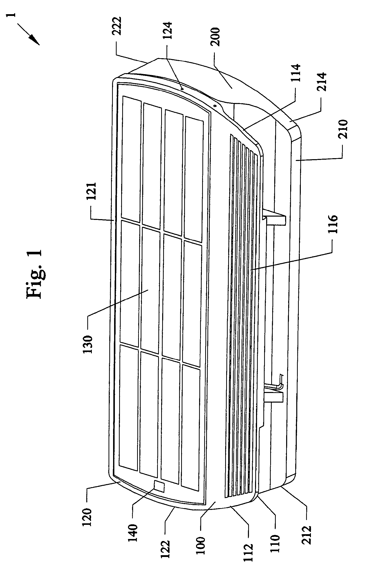
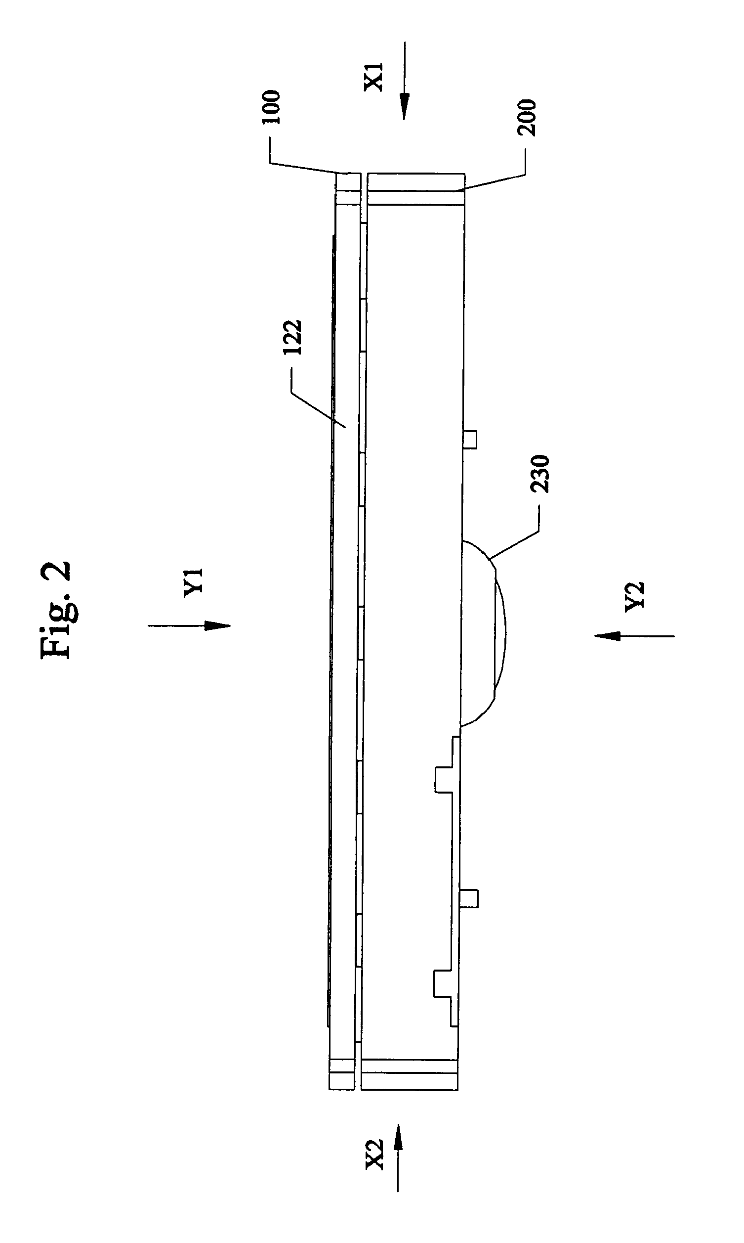
[0042]A listing of components will now be described.[0043]Housing 1[0044]Upper Half Section 100[0045]Rear end of cover lid 110[0046]Curved side ends 112, 114[0047]Raised or Grooved parallel gripping strips 116 on outer rear end[0048]Pivot attach members for spring 118[0049]Base of cover lid 120[0050]Front end 121[0051]Curved sides 122, 124[0052]Solar panel 130[0053]Photosensor 140[0054]Inside front gripping plate 150[0055]Gripping teeth / strips / grooves 156 on inner front plate[0056]Lower Half Section 200[0057]Rear end of bottom cover 210[0058]Curved side ends 212, 214[0059]Optional raised or grooved parallel gripping strips 216[0060]...


PUM


Abstract

Portable solar powered light sources, devices, apparatus, systems and methods of attaching and using the light source. The light sources can have a single small housing having an upper roof portion with an exposed solar cell, a photocell activator, and small housing. The housing can have two parts that pivot with one another so that a front end of the housing can be biased together by a spring, and the rear side having edges that are spaced apart. An operator can press the rear spaced apart edges together, to open the front end to slide about a support structure, such as an open umbrella fabric edge. The housing allows for the light source powered by batteries to be activated by the photocell during dark (night) conditions), with the light direction being adjustable underneath. During daylight, the solar cell receives sunlight to charge the batteries within the housing.

Description

[0001]This invention relates to lights, in particular to apparatus, devices and methods of attaching portable solar powered lights to outdoor umbrellas, tree branches, and manmade structures such as but not limited to porches, balconies, gazebos, and the like.BACKGROUND AND PRIOR ART[0002]Outdoor umbrellas, such as table umbrellas, beach umbrellas and the like, are popular for daytime activities, but can create shadows underneath that take away from their productive use. Furthermore, large table umbrellas, and beach umbrellas are often left in up positions after dark, which makes the space underneath difficult to illuminate. Providing artificial illumination sources such as candles, are easy to use, but must be handled with care since the flames can burn the umbrella. Popular electrically powered lights such as those formed from stringing electrical lines to power small lights and the like, can also be difficult to use, and are not practical in outdoor environments that have no powe...

Claims


Application Information

Patent Timeline
IPC IPC(8): F21L4/08A45B3/02
CPCA45B3/02F21V33/006F21V21/088F21S9/037F21V23/0464F21V23/04A45B2200/1018F21W2131/10F21Y2101/02F21Y2115/10Y02B20/72
Inventor WANG, SHOOUPYNG
Owner CHIEN LUEN INDS
Learn More