
Method and apparatus for illumination of drilling rigs and surrounding locations

a drilling rig and illumination technology, applied in the field of lighting assemblies, can solve the problems of lack of proper lighting and illumination in and around drilling rigs and/or surrounding areas, lack of quality and intensity of light emission to sufficiently illuminate said entire drilling rig and surrounding areas, and little, if any existing infrastructur

Active Publication Date: 2019-11-12
LOCATION ILLUMINATOR TECH LLC
View PDF15 Cites 5 Cited by
  • Summary
  • Abstract
  • Description
  • Claims
  • Application Information

AI Technical Summary

Benefits of technology

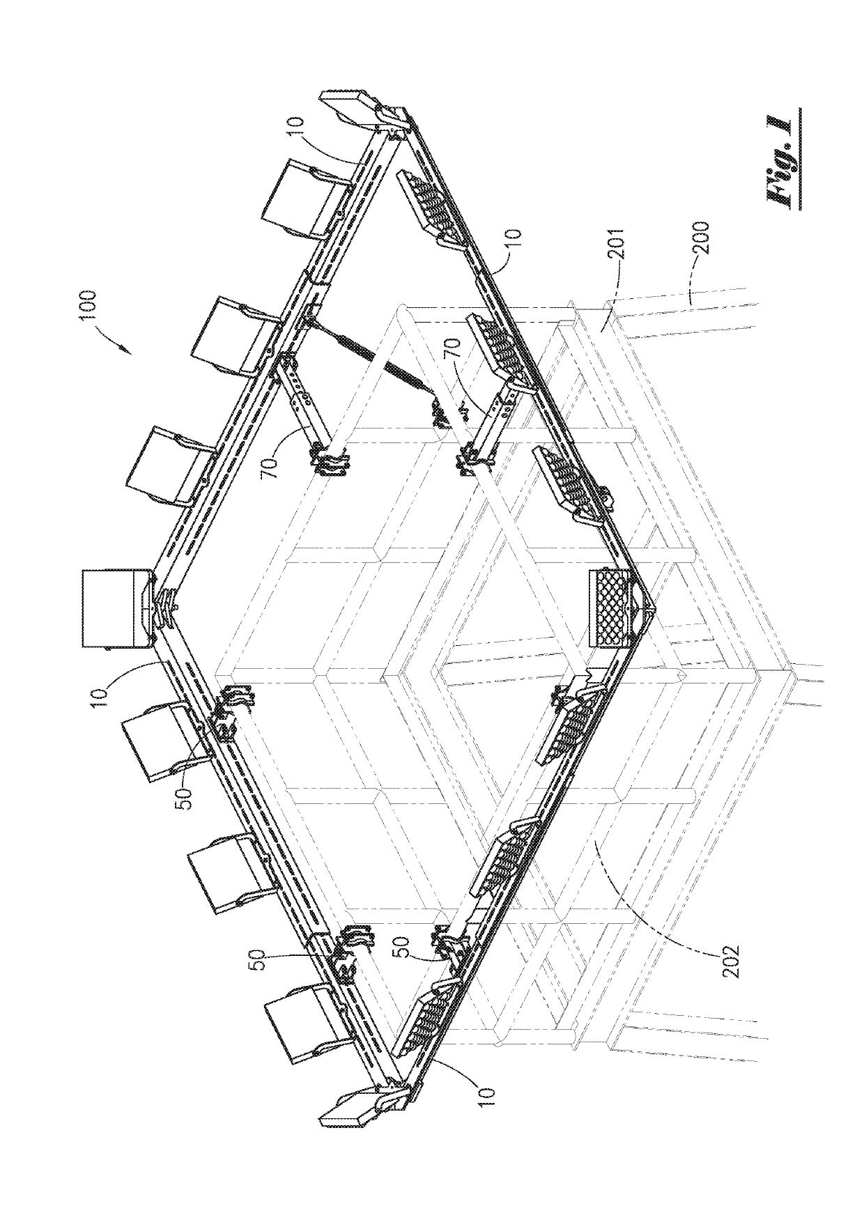
[0007]In a preferred embodiment, the present invention comprises a high intensity lighting assembly for use in illuminating a wide area such as, for example, a drilling rig location and surrounding vicinity. The lighting assembly of the present invention comprises a lighting system and mounting support frame assembly that can be operatively attached to a drilling rig, ideally on or near a crown of said derrick. In a preferred embodiment, said mounting support frame assembly can be beneficially attached to a hand rail of a derrick crown. When so configured, the lighting assembly of the present invention can provide illumination of substantially all work areas in and around such derrick, such as, for example, a rig floor, mud pits, pipe racks, equipment staging areas and portable personnel buildings.
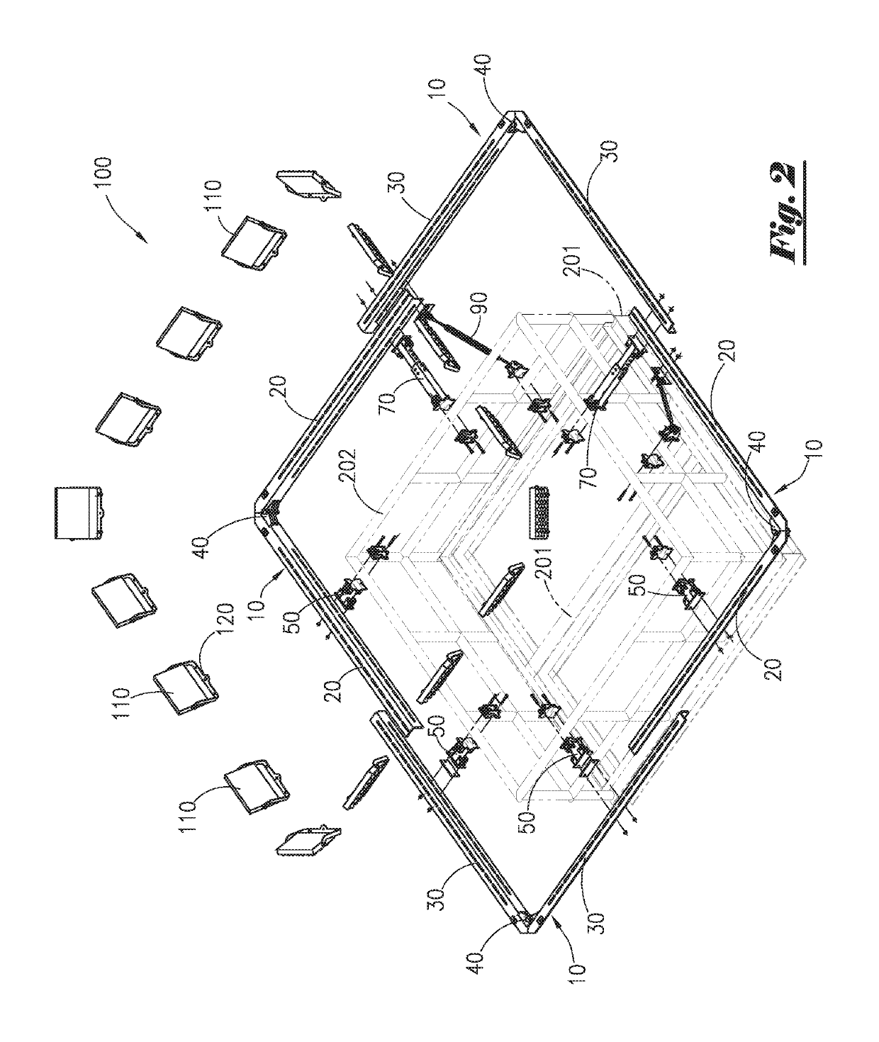
[0010]Said light-emitting fixtures can be selectively pointed or aimed in a substantially outward direction or other desired orientation relative to a drilling rig derrick crown. As such, said light-emitting fixtures can illuminate an entire area in and around said derrick and the surrounding location. As a result, the lighting assembly of the present invention provides for an easily attachable (and detachable) lighting system that can illuminate substantially all of a drilling rig or other work area.

Problems solved by technology

In many cases, such locations also have little, if any, existing infrastructure.
Such absence of surrounding development and existing infrastructure can result in a lack of proper lighting and illumination in and around a drilling rig and / or surrounding areas.
Such conventional lighting systems are typically not mounted at or near the upper extent of a conventional derrick due to the dissipation of light from such an elevated location.
However, due to their positioning and quality, such conventional lighting systems typically illuminate only localized or relatively small areas, and lack the quality and intensity of light emission to sufficiently illuminate said entire drilling rig and surrounding areas.

Method used


Image

  • Method and apparatus for illumination of drilling rigs and surrounding locations
  • Method and apparatus for illumination of drilling rigs and surrounding locations
  • Method and apparatus for illumination of drilling rigs and surrounding locations

Examples


Embodiment Construction

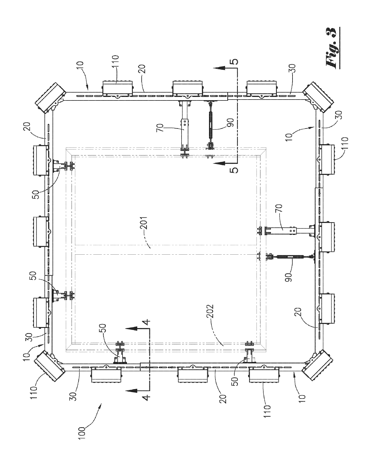
[0032]Referring to the drawings, FIG. 1 depicts an overhead perspective view of a lighting assembly 100 of the present invention deployed on a drilling rig derrick 200. As depicted in FIG. 1, drilling rig derrick 200 comprises a structural framework used to support a lifting apparatus and / or other components of a drilling rig. An upper section commonly referred to as a “crown”201 is disposed at or near the top of said derrick 200; on conventional drilling rigs, said crown 201 can support a crown block and / or sheave assembly (not pictured in FIG. 1) used with a rig's hoisting system.

[0033]Still referring to FIG. 1, a hand rail 202 is operationally attached to said crown 201. Among other benefits, said hand rail 202 acts as a safety fence or barrier for personnel working on or around said crown 201 which, when deployed, is typically positioned at an elevated location of 300 feet or more above a drilling rig. As depicted in FIG. 1, said hand rail 202 comprises a plurality of upwardly e...


PUM


Abstract

A lighting assembly can be quickly and efficiently mounted to a crown of a drilling rig derrick in order to provide wide-area illumination of the derrick and surrounding work location. An adjustable support frame member can be operationally attached to a hand rail of a derrick crown using fixed-length bracket members, adjustable-length bracket members and / or a combination(s) thereof. Lighting-emitting light source elements are adjustably attached to the support frame, and can be selectively aimed to direct light as desired.

Description

CROSS REFERENCES TO RELATED APPLICATION[0001]Priority of U.S. Provisional Patent Application Ser. No. 62 / 442,023, filed Jan. 4, 2017, incorporated herein by reference, is hereby claimed.STATEMENTS AS TO THE RIGHTS TO THE INVENTION MADE UNDER FEDERALLY SPONSORED RESEARCH AND DEVELOPMENT[0002]NONEBACKGROUND OF THE INVENTION1. Field of the Invention[0003]The present invention pertains to a lighting assembly for use in oil and gas and construction industries, and / or other applications, having a need for wide-area lighting and illumination. More particularly, the present invention pertains to a lighting assembly having an adjustable support frame assembly for attachably connecting said lighting assembly to a crown of a derrick of a drilling rig, thereby permitting illumination of a wide-area in and around said derrick with high quality light. More particularly still, the present invention pertains to a lighting assembly having number of beneficial advantages including, without limitation...

Claims


Application Information

Patent Timeline
Patent Type & Authority Patents(United States)
IPC IPC(8): F21V21/28E21B41/00F21S8/04E21B15/00F21V19/00F21V21/22
CPCF21V19/001F21V21/28F21S8/046E21B15/00E21B41/00F21V21/22F21S2/00F21V21/30F21W2131/1005F21W2131/402
Inventor CARROLL, CHARLES ALLEN
Owner LOCATION ILLUMINATOR TECH LLC
Learn More