Intramedullary pin for insertion into the medullary space of a femur

a technology of intramedullary pins and femurs, which is applied in the field of intramedullary pins for insertion into the medullary space of femurs, can solve the problems of irritating the surrounding tissue, using pure helical geometry in varying anatomy of bones, and undesired change in the height of the locking position, so as to prevent the surrounding tissue from being irritated

Active Publication Date: 2012-11-27
SYNTHES USA
View PDF16 Cites 9 Cited by
  • Summary
  • Abstract
  • Description
  • Claims
  • Application Information

AI Technical Summary

Benefits of technology

[0007]The present invention is to provide a remedy for the above-discussed disadvantages. It is an object of the invention to create an intramedullary pin where the distal locking holes are preferably parallel to the frontal plane or in lateral / medial alignment when the pin comes to rest in its final implantation depth range. The intramedullary pin may then be fixed in the proximal region by means of screws which are inserted through the neck of the femur into the head of the femur. To accomplish this, the implantation depth of the pin must be such that the screws may be passed centrally through the neck of the femur. The neck of the femur and head are, however, rotated relative to the frontal plane about the longitudinal axis of the femur. This rotation is described as the anteversion angle, meaning that the pin must be adapted to the anatomically changing anteversion angles by rotation of the pin about its longitudinal axis. This is intended to ensure that the screws may be placed centrally through the neck of the femur and centrally in the head. Furthermore, the proximal pin end should be flush with the surrounding cortex or deeper. This is intended to prevent the surrounding tissue from being irritated by the proximal pin end.
[0008]It is therefore an object to provide an intramedullary pin that need not have an adapted geometry for every femur bone exhibiting different growth, in order to fulfill the abovementioned conditions. The present invention accomplishes the objective set out above with an intramedullary pin where the end of the helical shape are modified. Specifically, the proximal end of the pin is curved in a plane, while the distal end remains straight. This ensures that, on reaching the final implantation depth range, the intramedullary pin ceases to rotate by itself. In the final implantation depth range, the pin may be displaced along its longitudinal axis without change of rotation. The pin may nevertheless be arbitrarily rotated about its longitudinal axis without changing its implantation depth.

Problems solved by technology

There are disadvantages to using a pure helical geometry in varying anatomy of bones.
This consequently results in an undesired change of height of the locking position.
In another instance, if only rotation is to be corrected, this can lead to a displacement of the implant depth of the pin and hence to an undesired change in the height of the locking position.
This, however, results in an undesired continuation of the rotational movement.

Method used


Image

  • Intramedullary pin for insertion into the medullary space of a femur
  • Intramedullary pin for insertion into the medullary space of a femur
  • Intramedullary pin for insertion into the medullary space of a femur

Examples


Embodiment Construction

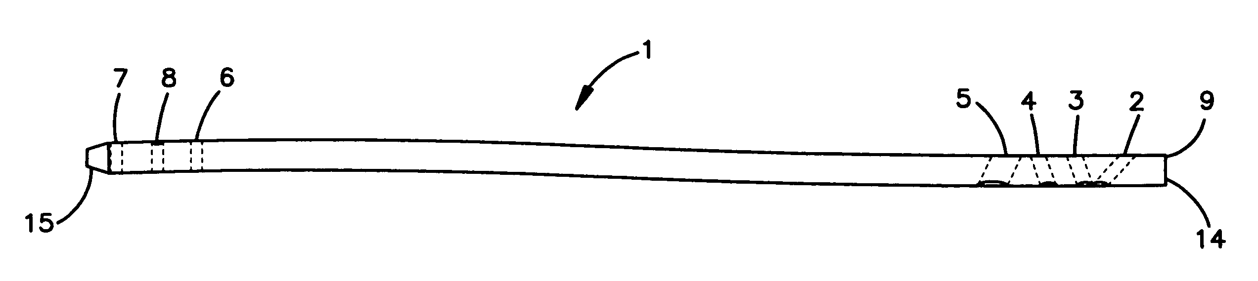
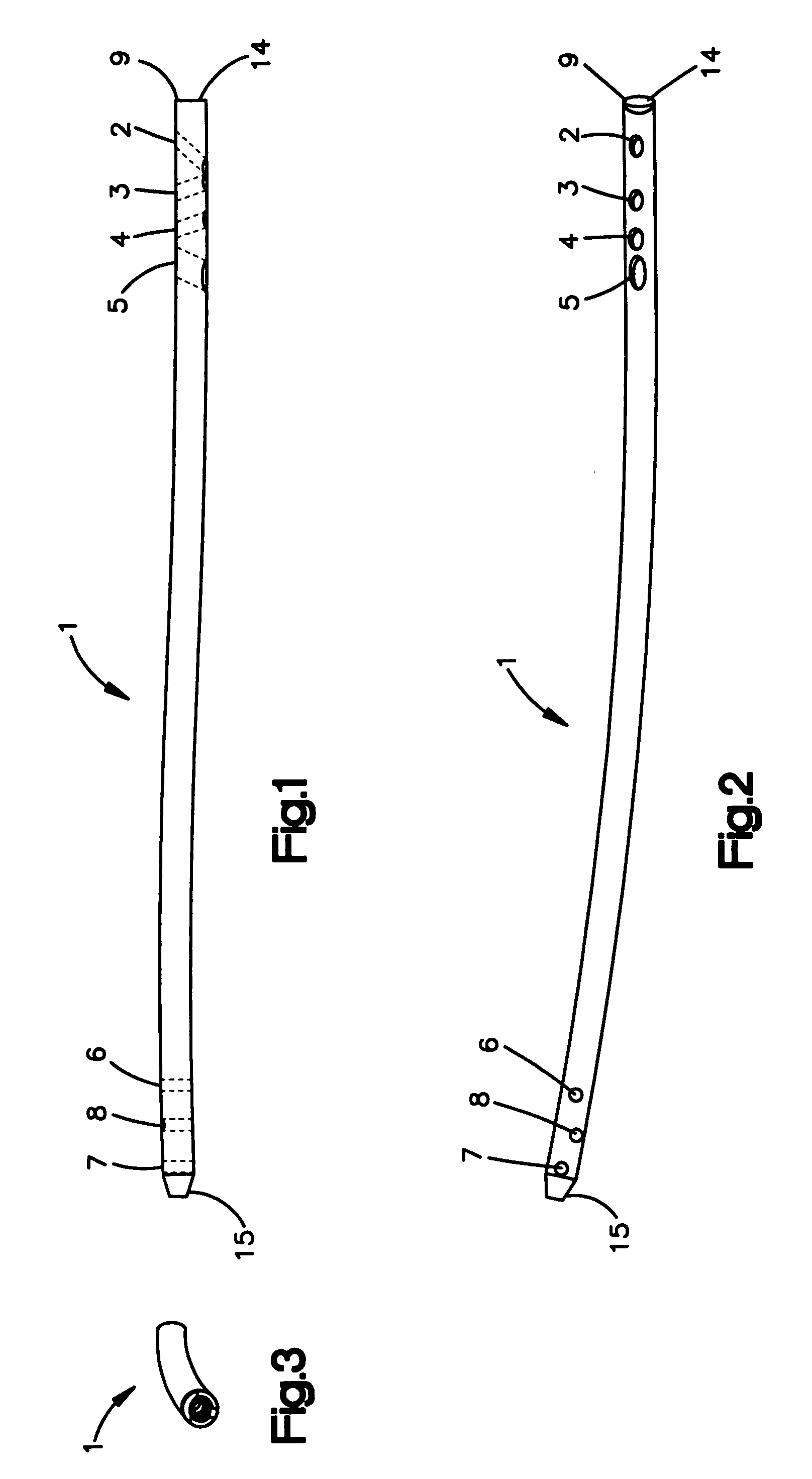
[0031]FIGS. 1-3 depict an intramedullary pin 1 in three views. The intramedullary pin 1 has a proximal end 14 and a distal end 15. The shaft of the pin 1 is generally cylindrical in shape. The proximal end 14 may be curved in a lateral-posterior direction, while the distal end 15 may be straight or at least partly straight. Proximal and distal end planes of the pin may be rotated about 60°-110°, preferably 70°-90° and in particular 80° relative to one another. In one embodiment, the radius is between about 300-1300 mm, preferably about 900-1200 mm and in particular about 1100 mm. The length of the proximal radius corresponds to the lateral contact surface with the cortex which is about 300-1000 mm, preferably about 600-800 mm, and in particular 700 mm.

[0032]The length of the distal straight section may correspond to the depth to which the distal pin end penetrates into the distal spongiosa structure. The length may be about 35-70 mm, preferably about 40-60 mm, and in particular abou...


PUM


Abstract

An intramedullary pin for insertion into the medullary space of the femur through the lateral compacta of the trochanter major. The pin has a proximal pin section and an adjoining distal pin section. Each pin section includes one or more bores for one or more bone screws. The proximal pin section has at least one bore running obliquely to the longitudinal axis, so that bone screws can be inserted through the bore into the head of the femur, or a screw can be inserted in the antegrade direction through the bore. The distal pin section is at least partly straight and the proximal pin section has a curvature in the lateral-posterior direction.

Description

CROSS REFERENCE TO RELATED APPLICATION[0001]This application is a continuation of International Patent Application No. PCT / IB2004 / 003425, filed Oct. 20, 2004, the entire contents of which is expressly incorporated herein by reference.TECHNICAL FIELD[0002]The present invention relates an intramedullary pin for insertion into the medullary space of a femur.BACKGROUND OF THE INVENTION[0003]It is known in the art to use intramedullary pins. U.S. Pat. No. 6,461,360B1 describes an intramedullary pin for osteosynthesis. Before insertion into a femur, the intramedullary pin has, at its distal end, in the sagittal plane, a curvature which corresponds to the counter-curvature of the femur. The proximal end substantially has a continuous curve with constant radius of curvature in the frontal plane.[0004]U.S. Pat. No. 6,010,506 discloses a hybrid pin having different radii, all of which extend in a plane.[0005]International publication WO 02089683 discloses an intramedullary pin using helix geo...

Claims


Application Information

Patent Timeline
Patent Type & Authority Patents(United States)
IPC IPC(8): A61B17/72
CPCA61B17/72A61B17/744A61B17/7283A61B17/74A61B17/86A61B17/7241
Inventor KAUP, THOMAS
Owner SYNTHES USA
Why Eureka
Try Eureka