Twin internal ion source for particle beam production with a cyclotron

a cyclotron and internal ion source technology, applied in the direction of magnetic resonance accelerators, electrical discharge tubes, electrical apparatus, etc., can solve the problems of inability to meet the needs of particle beam production, so as to avoid particle loss, reduce the loss of particle beam during the first turn of acceleration, and increase the distance

Active Publication Date: 2012-12-04
ION BEAM APPL
View PDF5 Cites 4 Cited by
  • Summary
  • Abstract
  • Description
  • Claims
  • Application Information

AI Technical Summary

Benefits of technology

[0020]According to one embodiment, the cyclotron is further characterized by an optimized close geometry of the different elements within the central region of the cyclotron. The distance of the first internal ion source (1) and the second internal ion source (2) with respect to the central vertical axis are minimized to avoid particle losses during the first turn of acceleration. According to this embodiment, the distance of said first internal ion source (1) and said second internal ion source (2) with respect to said central vertical axis is reduced in order to increase the distance between the beam from said first / second internal ion source after travelling 180° and said second / first internal ion source, whereby particle losses during the first turn of acceleration are minimized. In other words, the sources are positioned at the minimum distance which is technically possible, in order to ensure that there is no collision between particles produced by one source with the body of the other source. When the sources are placed symmetrically with respect to the central axis of the cyclotron, a possible collision takes place when the particles have traveled 180° from one source to the other. The minimum technically possible distance depends on the shape of the sources and electrodes, and may be determined by the minimum required distance between the particle sources and the Dee-electrodes.
[0021]According to another embodiment, the cyclotron of the invention is further characterized by an adaptation and optimization of the shape of first internal ion source (1) and the second internal ion source (2) to avoid particle losses during the first turn of acceleration. According to this embodiment, the body of said first internal ion source (1) and said second internal ion source (2) comprises a notch (40) at the periphery of said body oriented away from the central vertical axis of said cyclotron. Said notch is arranged to avoid collision of particles produced by one source, with the body of the other source.
[0022]According to yet another embodiment, the cyclotron is characterized by an adaptation and optimization of the shape of the counter-Dee electrode assembly (4), and possibly also of the Dee-electrode assembly, in order to improve the acceleration field in-between the gaps (5). According to this embodiment, corners in said counter-Dee electrode assembly (4) at positions where said particle beams cross said gap (5) are reduced, whereby the field-quality of said electric field in the gaps is improved. In other words, the counter-Dee electrode (4) assembly, and possibly also the Dee-electrode assembly (3), is configured in such a way that the crossings of the gap (5) by the particles takes place at areas where there is no corner or bend in said gap (5).

Problems solved by technology

The internal ion sources in a cyclotron are fragile and due to wear need to be replaced regularly.
Replacing an internal ion source is cumbersome and takes time: the vacuum is broken, the cyclotron is opened, the ion source is replaced, the cyclotron is closed and the cyclotron is pumped down until good vacuum is obtained.
Moreover, during the maintenance process when the internal ion source needs to be replaced, personnel performing the maintenance is exposed to radiation from activated materials.
At present, no practical solution has been proposed so far to increase on the one hand the uptime and reliability of operation of a cyclotron having an internal ion source and on the other hand reduce the exposure of the personnel to radiation during the maintenance process.

Method used


Image

  • Twin internal ion source for particle beam production with a cyclotron
  • Twin internal ion source for particle beam production with a cyclotron
  • Twin internal ion source for particle beam production with a cyclotron

Examples


Embodiment Construction

[0030]The present invention will be now described in detail in relation to the appended drawings. However, it is evident that a person skilled in the art may conceive several equivalent embodiments or other ways of executing the present invention. The detailed description, the drawings and the calculation results are given with respect to the installation of two internal H− proton ion sources in a 18 MeV cyclotron. It is evident that the present invention can be applied to any type of cyclotron. The spirit and the scope of the present invention are therefore limited only by the terms of the claims.

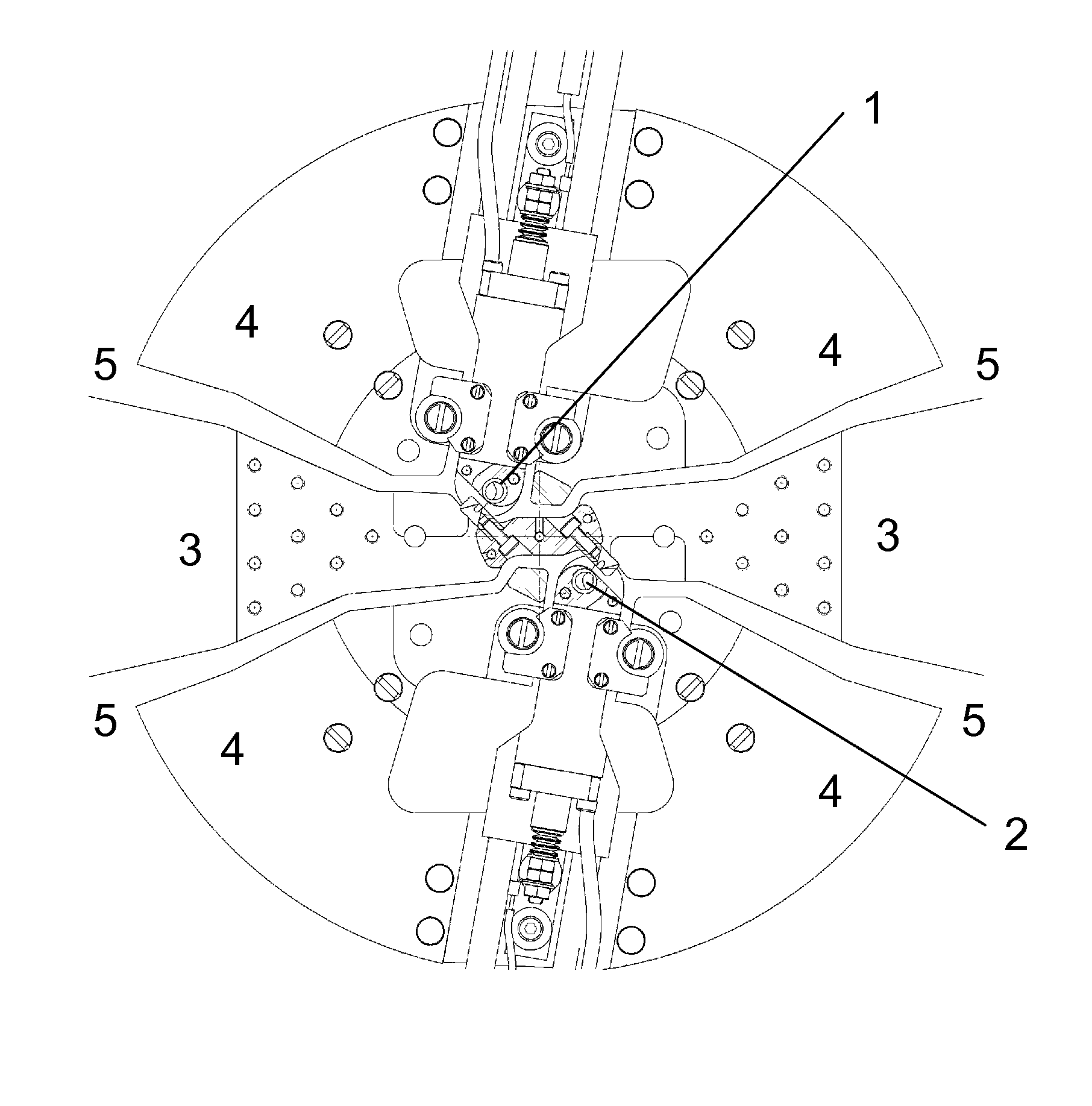
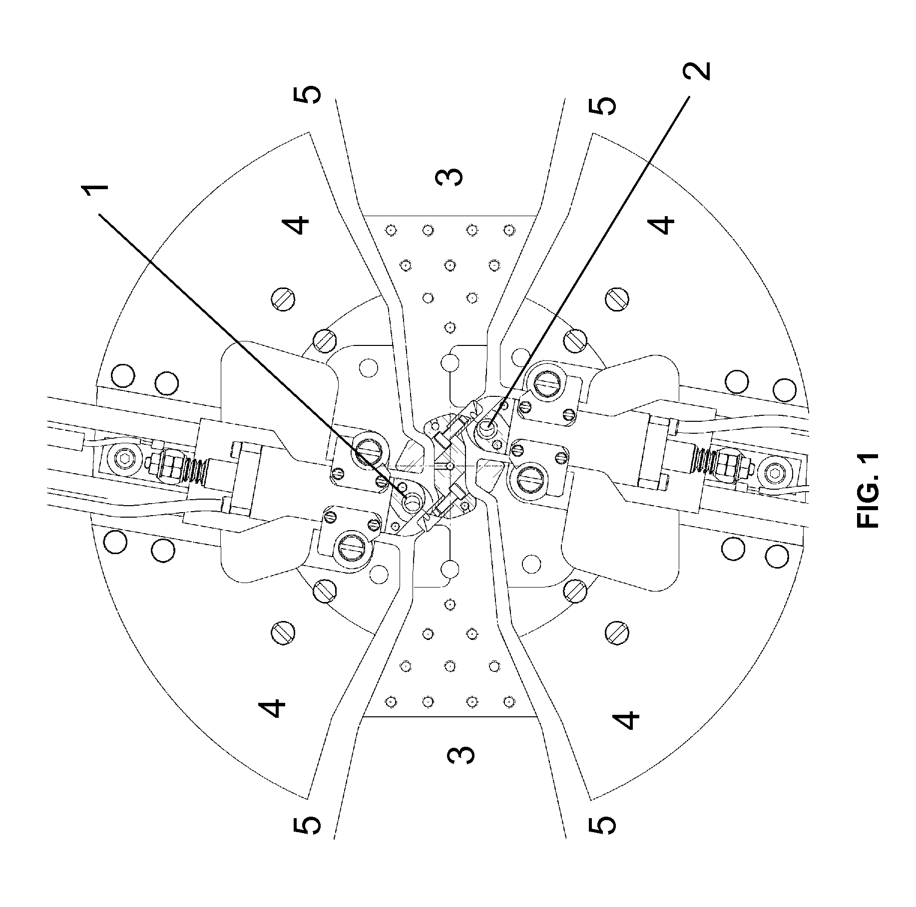
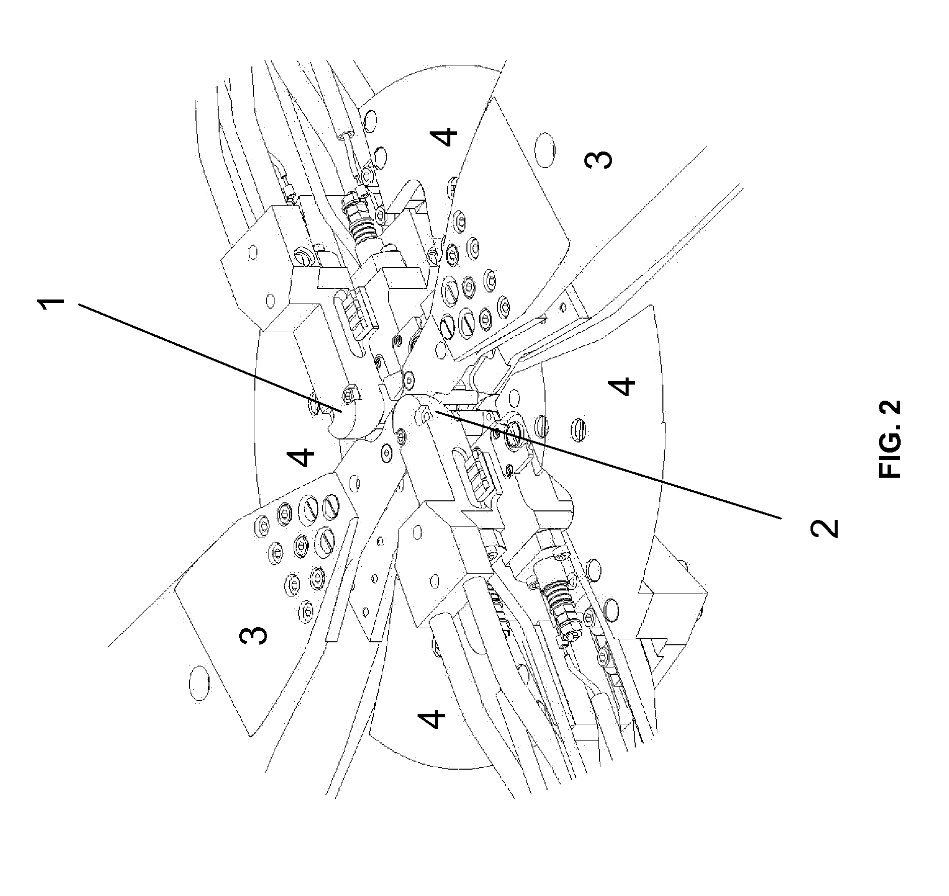
[0031]FIG. 1 shows a representation of the central region of a cyclotron according to a preferred embodiment of the present invention. The central region of this cyclotron comprises:[0032]a first ion source (1) for producing charged particles[0033]a second ion source (2) for producing charged particles, the second ion source (2) being identical to the first ion source (1)[0034]a Dee electr...


PUM


Abstract

The present invention relates to a cyclotron including two internal ion sources for the production of the same particles. The second ion source can be used as a spare ion source which strongly increases the uptime and the reliability of the cyclotron and reduces the maintenance interventions. Advantageously, the cyclotron is further characterized by an optimized close geometry of the different elements within the central region of the cyclotron. The cyclotron of the invention may be further characterized by an adaptation and optimization of the shape of first and second internal ion source to avoid particle losses during the first turn of acceleration. The cyclotron may be further characterized by an adaptation and optimization of the shape of the counter-Dee electrode assembly and possibly the Dee-electrode assembly in order to improve the acceleration field in-between the gaps.

Description

CROSS REFERENCE TO RELATED APPLICATIONS[0001]This application is a national phase application of International Application No. PCT / EP2009 / 056673, filed May 29, 2009, designating the United States and claiming priority to European Patent Application No. 08157892.4, filed Jun. 9, 2008, both of which are incorporated by reference herein in their entirety.FIELD OF THE INVENTION[0002]The present invention relates to the field of cyclotron accelerators. More particularly, this invention relates to an internal ion source assembly for a cyclotron accelerator.STATE OF THE ART[0003]A cyclotron is a re-circulation particle accelerator, which operates under high vacuum and in which charged particles, generated by an ion source, are accelerated in a circular motion. This is achieved by using on the one hand a magnetic field which causes the particles, coming from said source, to follow a circular path in a plane perpendicular to said magnetic field, and on the other hand a high-frequency alterna...

Claims


Application Information

Patent Timeline
Patent Type & Authority Patents(United States)
IPC IPC(8): H05H13/00
CPCH05H13/00
Inventor KLEEVEN, WILLEMGHYOOT, MICHELABS, MICHEL
Owner ION BEAM APPL
Why Eureka
Try Eureka