Leg sling device

a leg sling and leg technology, applied in the field of leg sling devices, can solve the problems of injury to legs, feet, ankles, knees, and individuals who cannot lift their legs to walk uphill or up stairs

Inactive Publication Date: 2013-01-08
SEVERENCE THOMAS A
View PDF17 Cites 6 Cited by
  • Summary
  • Abstract
  • Description
  • Claims
  • Application Information

AI Technical Summary

Problems solved by technology

Individuals with injured legs, feet, ankles, and knees can have great difficulty lifting their legs to walk uphill or up stairs.

Method used


Image

  • Leg sling device
  • Leg sling device
  • Leg sling device

Examples


Embodiment Construction

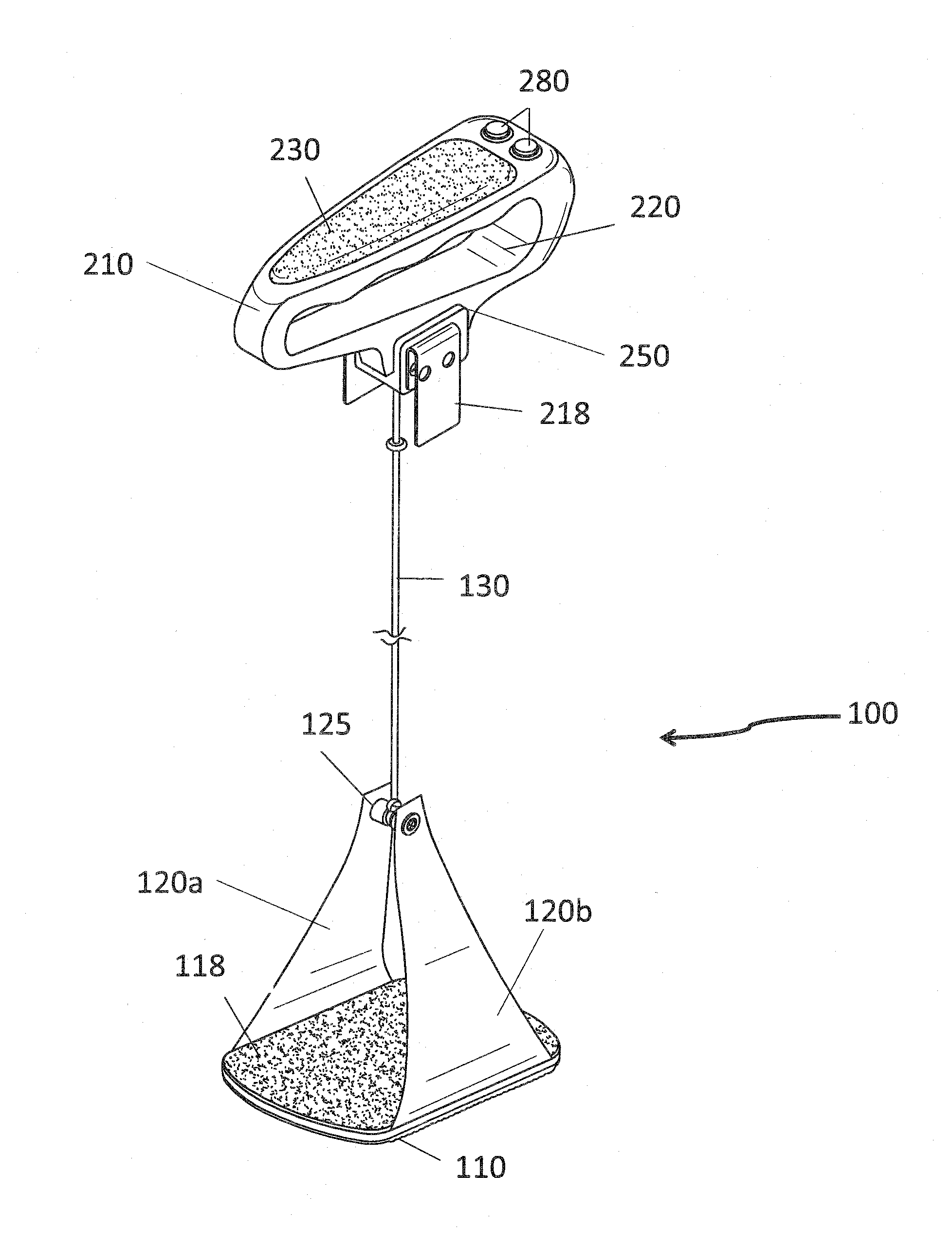
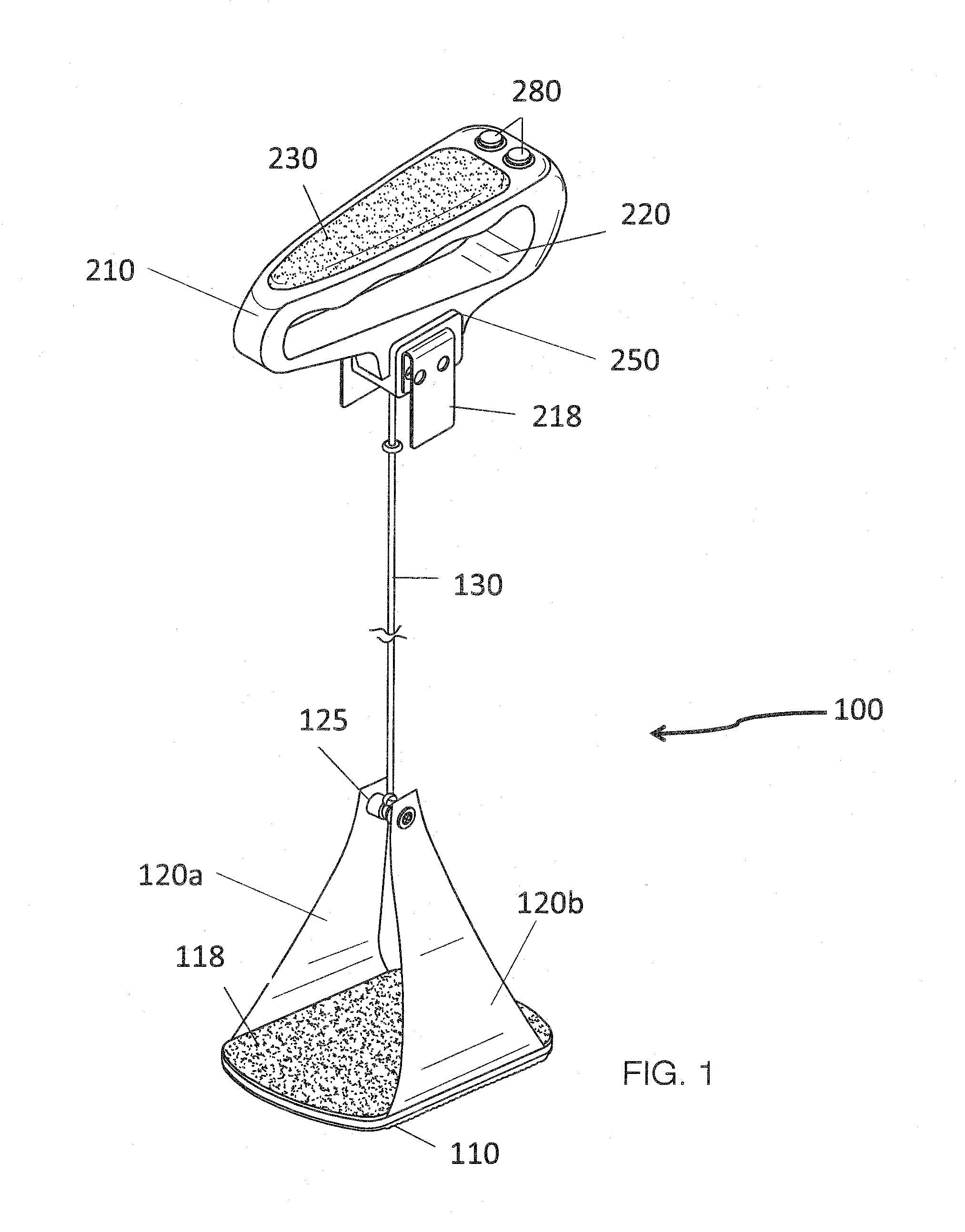
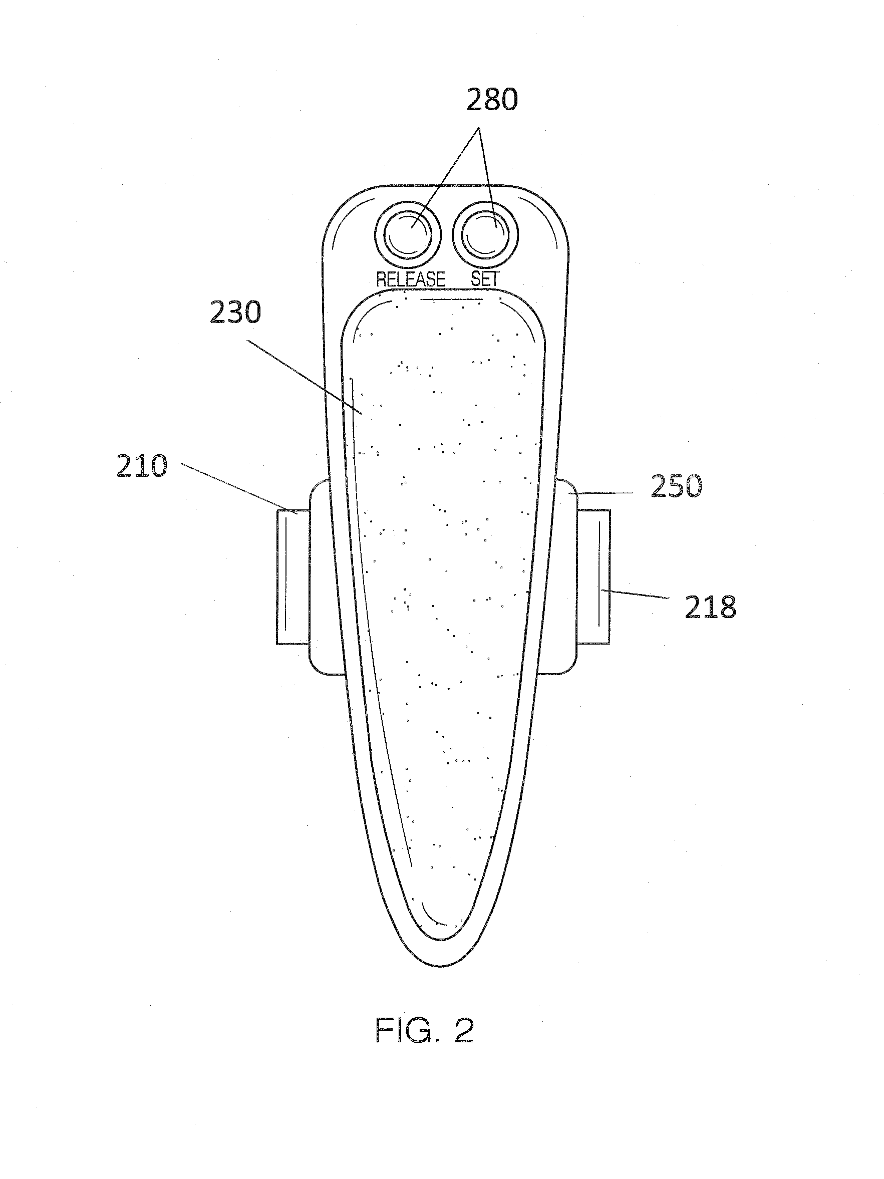
[0009]Referring now to FIGS. 1-5, the present invention features a leg sling device 100 for helping to lift a user's leg when walking or climbing stairs. Without wishing to limit the present invention to any theory or mechanism, it is believed that the leg sling device 100 of the present invention is advantageous because it can help take pressure off pressing down on a cane when walking.

[0010]The leg sling device 100 of the present invention comprises a foot platform 110 on which a user can place his / her foot. A first half strap 120a extends upwardly from a first side of the foot platform 110 and a second half strap 120b extends upwardly from a second side of the foot platform 110. The half straps 120 meet and connect a distance above the foot platform 110. In some embodiments, the half straps 120 are connected via a connecting component (e.g., a barrel 125). In some embodiments, the foot platform 110 comprises side walls (e.g., volcano-shaped side walls).

[0011]As shown in FIG. 4, t...


PUM


Abstract

A leg sling device featuring a foot platform for supporting a user's foot; two half straps extending upwardly from sides of the foot platform, the tops of the half straps connect via a barrel; a hand base having an opening for accommodate the user's fingers; a reel disposed in the hand base; a cable having a first end wrapped around the reel in the hand base and a second end attached to the barrel that connects the half straps; and a motor and control buttons operatively connected to the reel, the motor and control buttons function to rotate the reel in a first direction to retract the cable into the hand base thereby raising the foot platform and a second direction to extend the cable out of the hand base thereby lowering the foot platform.

Description

FIELD OF THE INVENTION[0001]The present invention is directed to a sling-like device for lifting a user's leg, for example when the user is walking or climbing stairs.BACKGROUND OF THE INVENTION[0002]Individuals with injured legs, feet, ankles, and knees can have great difficulty lifting their legs to walk uphill or up stairs. The present invention features a leg sling device. The leg sling device of the present invention helps a user walk more easily with an injured leg and can help eliminate the need for a user to push down on a cane when walking uphill or up stairs. In some embodiments, the device can help relieve pain.[0003]Any feature or combination of features described herein are included within the scope of the present invention provided that the features included in any such combination are not mutually inconsistent as will be apparent from the context, this specification, and the knowledge of one of ordinary skill in the art. Additional advantages and aspects of the presen...

Claims


Application Information

Patent Timeline
Patent Type & Authority Patents(United States)
IPC IPC(8): A61H1/00
CPCA61H1/0262A61H3/00A61H2201/0153A61H2003/001A61H2201/0157A61H2201/1215A61H2201/1642A61H2201/1664A61H2201/5025
Inventor SEVERENCE, THOMAS A.
Owner SEVERENCE THOMAS A
Why Eureka
Try Eureka