Lightweight under engine shield

a technology of lightweight under engine shield and engine, which is applied in the direction of roofs, weaving, transportation and packaging, etc., can solve the problems of frequent rigidity and difficulty in installation and repair

Active Publication Date: 2013-02-05
FORD GLOBAL TECH LLC
View PDF4 Cites 18 Cited by
  • Summary
  • Abstract
  • Description
  • Claims
  • Application Information

AI Technical Summary

Problems solved by technology

The shields are frequently rigid, very heavy, and often times do not pass air into the engine compartment.
The heavy weight of the shields can make them difficult to install and repair.

Method used


Image

  • Lightweight under engine shield
  • Lightweight under engine shield
  • Lightweight under engine shield

Examples


Embodiment Construction

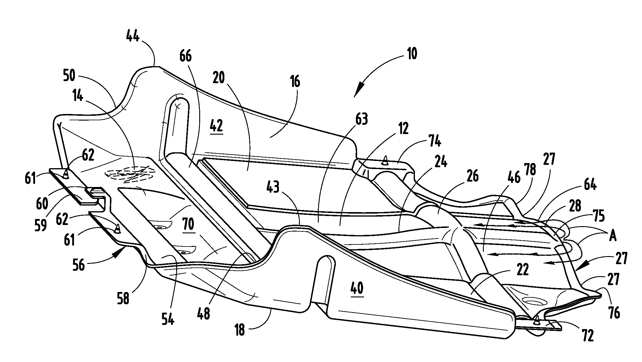
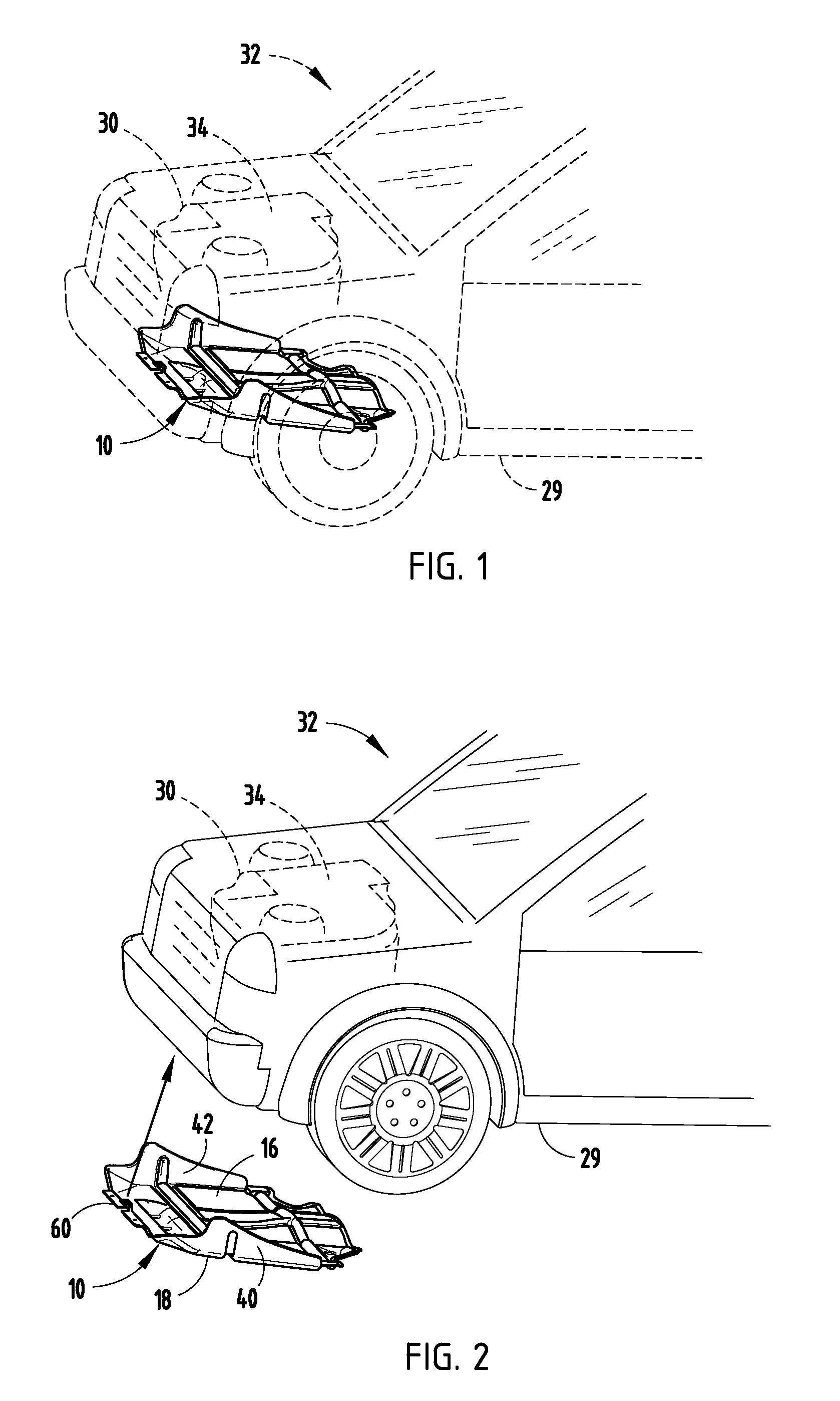
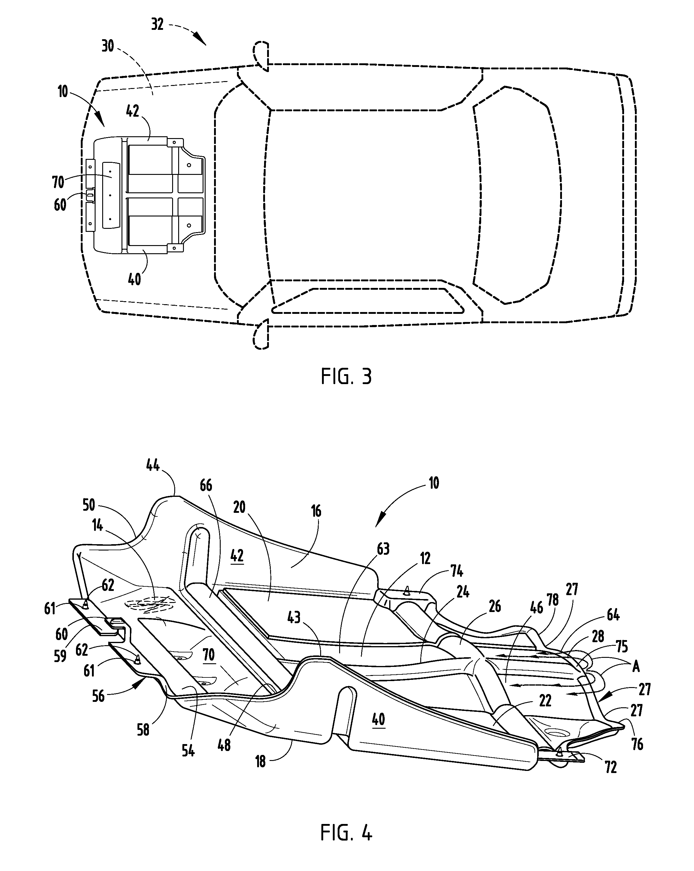
[0016]For purposes of description herein, the terms “upper,”“lower,”“right,”“left,”“rear,”“front,”“vertical,”“horizontal,” and derivatives thereof shall relate to the invention as oriented in FIG. 1. However, it is to be understood that the invention may assume various alternative orientations, except where expressly specified to the contrary. It is also to be understood that the specific devices and processes illustrated in the attached drawings, and described in the following specification are simply exemplary embodiments of the inventive concepts defined in the appended claims. Hence, specific dimensions and other physical characteristics relating to the embodiments disclosed herein are not to be considered as limiting, unless the claims expressly state otherwise.

[0017]Referring now to FIGS. 1-4, the reference numeral 10 generally designates a heat shield having a body portion 12 formed from a non-woven material 14. The body portion 12 includes an internal side 16 and an external...


PUM


Abstract

A heat shield having a body portion formed from a non-woven material and having an internal side and an external side. First and second heat patches are disposed on the internal side of the body portion. A first channel is disposed between the first and second heat patches and a second channel is disposed under the first and second heat patches. A convex air drafting portion is disposed on a rearward side of said vehicular heat shield.

Description

FIELD OF THE INVENTION[0001]The present invention generally relates to an under engine shield, and more particularly relates to a non-woven lightweight under engine shield with enhanced engine cooling characteristics.BACKGROUND OF THE PRESENT INVENTION[0002]Under engine shields are generally found under a vehicle to protect the engine and enhance aerodynamic properties. The shields are frequently rigid, very heavy, and often times do not pass air into the engine compartment. The heavy weight of the shields can make them difficult to install and repair.SUMMARY OF THE PRESENT INVENTION[0003]One aspect of the present invention includes a heat shield having a body portion formed from a non-woven material and having an internal side and an external side. First and second heat patches are disposed on the internal side of the body portion. A first channel is disposed between the first and second heat patches and a second channel is disposed under the first and second heat patches. A convex...

Claims


Application Information

Patent Timeline
Patent Type & Authority Patents(United States)
IPC IPC(8): B62D21/00
CPCB60R19/54Y10T428/24636Y10T428/2419B60R13/0861
Inventor GLICKMAN, DAVID BRIAN
Owner FORD GLOBAL TECH LLC
Why Eureka
Try Eureka