Surgical end effector having buttress retention features

a technology of buttress material and surgical end, which is applied in the direction of surgical staples, paper/cardboard containers, applications, etc., can solve the problems of surgeons spending valuable time, surgeons being unable to attach pieces of buttress material, and improper formation of staples within tissu

Active Publication Date: 2013-02-12
CILAG GMBH INT
View PDF1213 Cites 2067 Cited by
  • Summary
  • Abstract
  • Description
  • Claims
  • Application Information

AI Technical Summary

Benefits of technology

[0009]In at least one form of the invention, a piece of buttress material can be releasably attached to a sleeve, wherein the sleeve can be configured to be slid over at least one of the staple cartridge and the anvil of an end-effector. In at least one embodiment, the piece of buttress material can include a side portion which can be attached to the sleeve and, in addition, a body portion configured to be engaged with staples when the staples are deployed from the staple cartridge. In such an embodiment, the side portion can be used to releasably retain the body portion to the sleeve. In at least one embodiment, a recess and / or perforation can be defined in the piece of buttress material intermediate the side portion and the body portion, for example, such that the body portion can be separated from the side portion. In at least one embodiment, as a result, the perforation and / or recess can allow the sleeve to be removed from the buttress material after the staples have been deployed into the body portion.
[0012]In at least one form of the invention, a piece of buttress material configured to be releasably attached to an end-effector can include an unactivated adhesive. In various embodiments, a surgeon can position and align the piece of buttress material on the end-effector multiple times without the un-activated adhesive bonding to the end-effector. Once the surgeon is satisfied with the alignment of the piece of buttress material on the end-effector, the surgeon can then apply a reactant to the un-activated adhesive. In various embodiments, the reactant can activate the adhesive and cause the adhesive to releasably bond the piece of buttress material to a portion of the end-effector. In at least one embodiment, the piece of buttress material can include a recess configured to receive an applicator such that the application of the reactant to the un-activated adhesive can be facilitated.
[0013]In at least one form of the invention, an end effector can include a retractable retention member for retaining a piece of buttress material on an end-effector. In various embodiments, the retention member can be movable between a first, or distal, position and a second, or proximal, position. In at least one embodiment, the flexible member can be operably engaged with a handle portion such that a surgeon can utilize the handle portion to retract the flexible member relative to the end-effector. In various embodiments, the flexible member can hold the piece of buttress material in position while staples are deployed through the buttress material. In at least one embodiment, the retention member can be retracted relative to the end effector such that the buttress material can be disengaged from the end effector and the end effector can be removed from the surgical site.

Problems solved by technology

In some circumstances, the layers of tissue can be relatively thin, can have a high fluid content, and / or can have a non-uniform thickness, which can cause the staples to be improperly formed within the tissue.
In various embodiments, a piece of buttress material can be difficult for a surgeon to attach to the jaw members of an end-effector.
As a result, the surgeon can spend valuable time positioning and aligning a piece of buttress material on a jaw member of an end-effector.

Method used


Image

  • Surgical end effector having buttress retention features
  • Surgical end effector having buttress retention features
  • Surgical end effector having buttress retention features

Examples


Embodiment Construction

[0077]Certain exemplary embodiments will now be described to provide an overall understanding of the principles of the structure, function, manufacture, and use of the devices and methods disclosed herein. One or more examples of these embodiments are illustrated in the accompanying drawings. Those of ordinary skill in the art will understand that the devices and methods specifically described herein and illustrated in the accompanying drawings are non-limiting exemplary embodiments and that the scope of the various embodiments of the present invention is defined solely by the claims. The features illustrated or described in connection with one exemplary embodiment may be combined with the features of other embodiments. Such modifications and variations are intended to be included within the scope of the present invention.

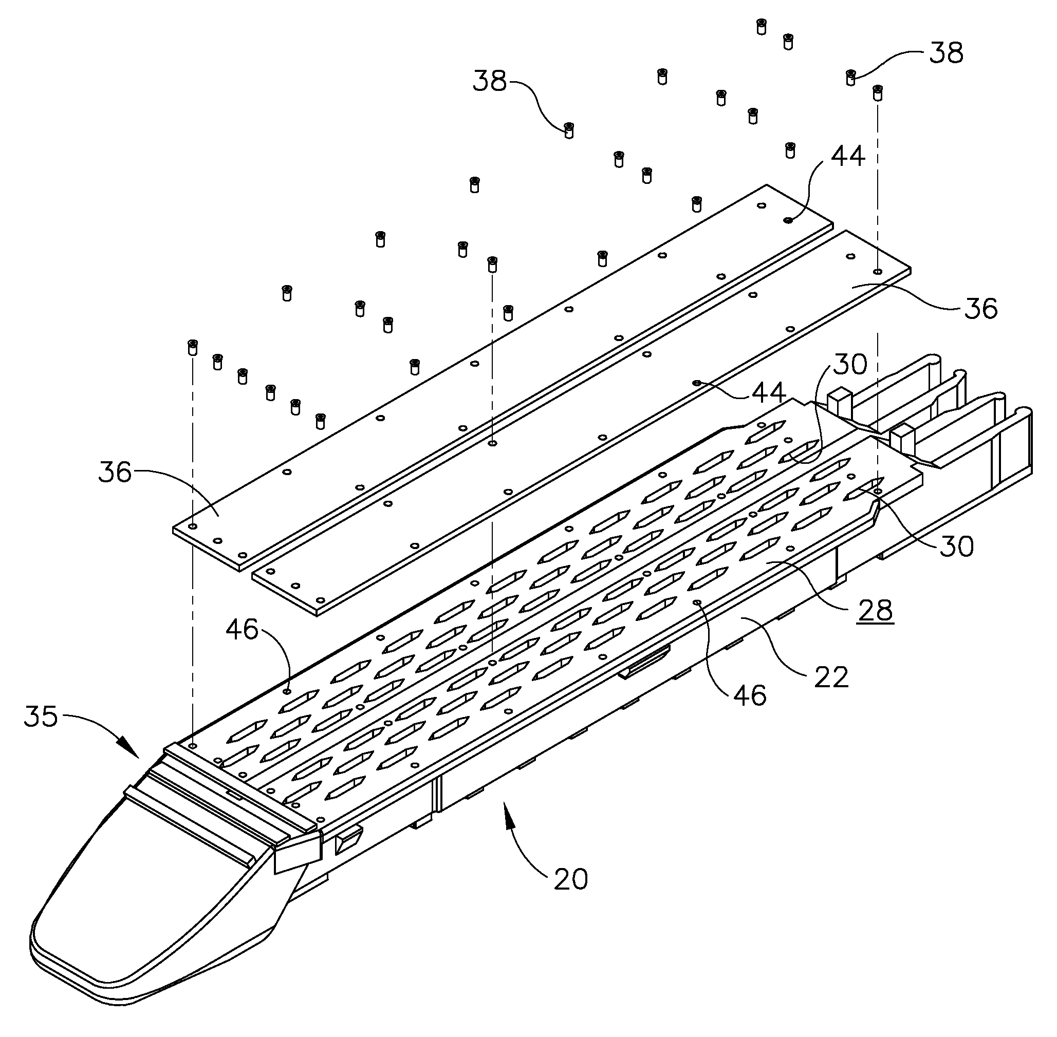
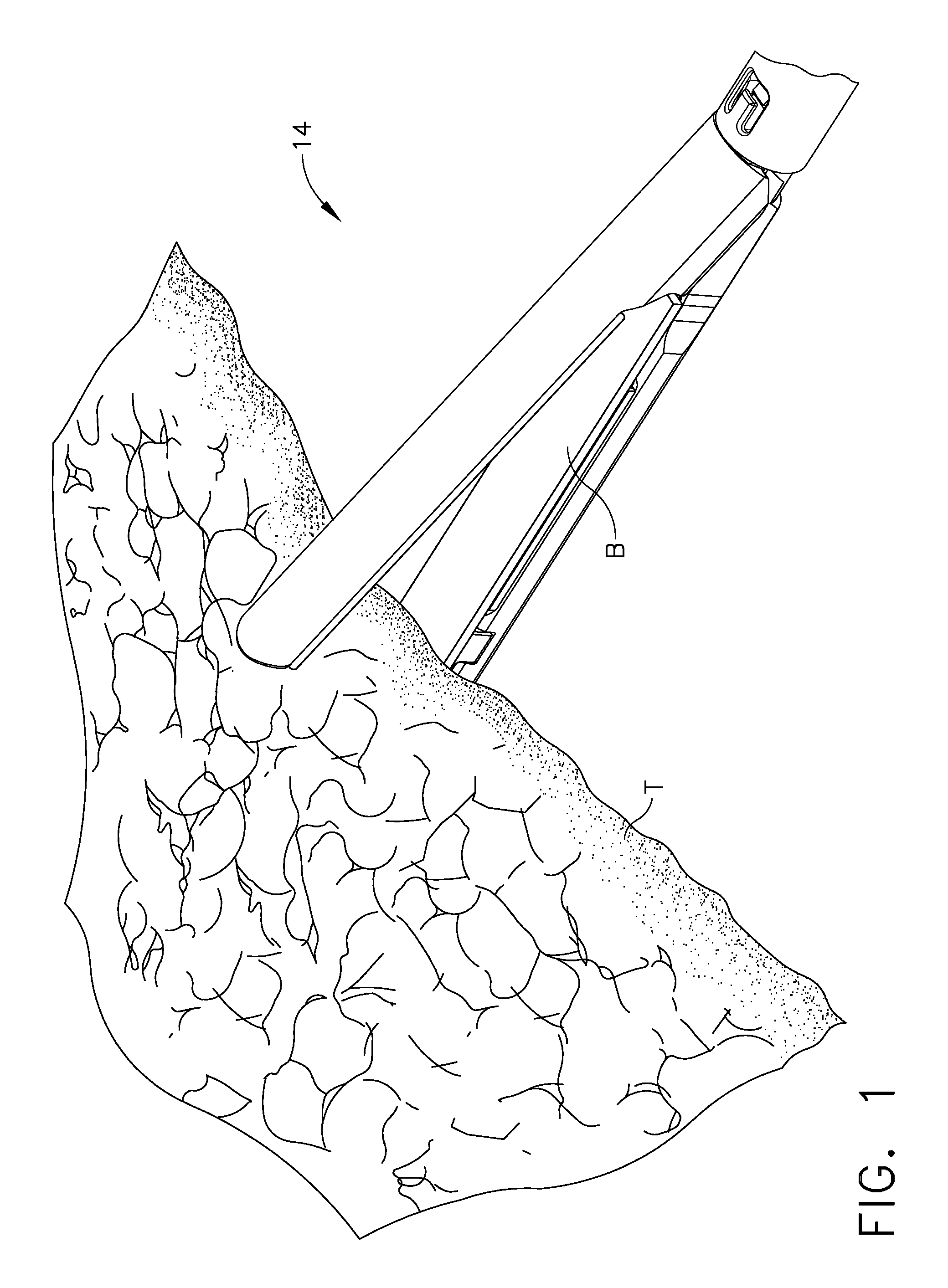
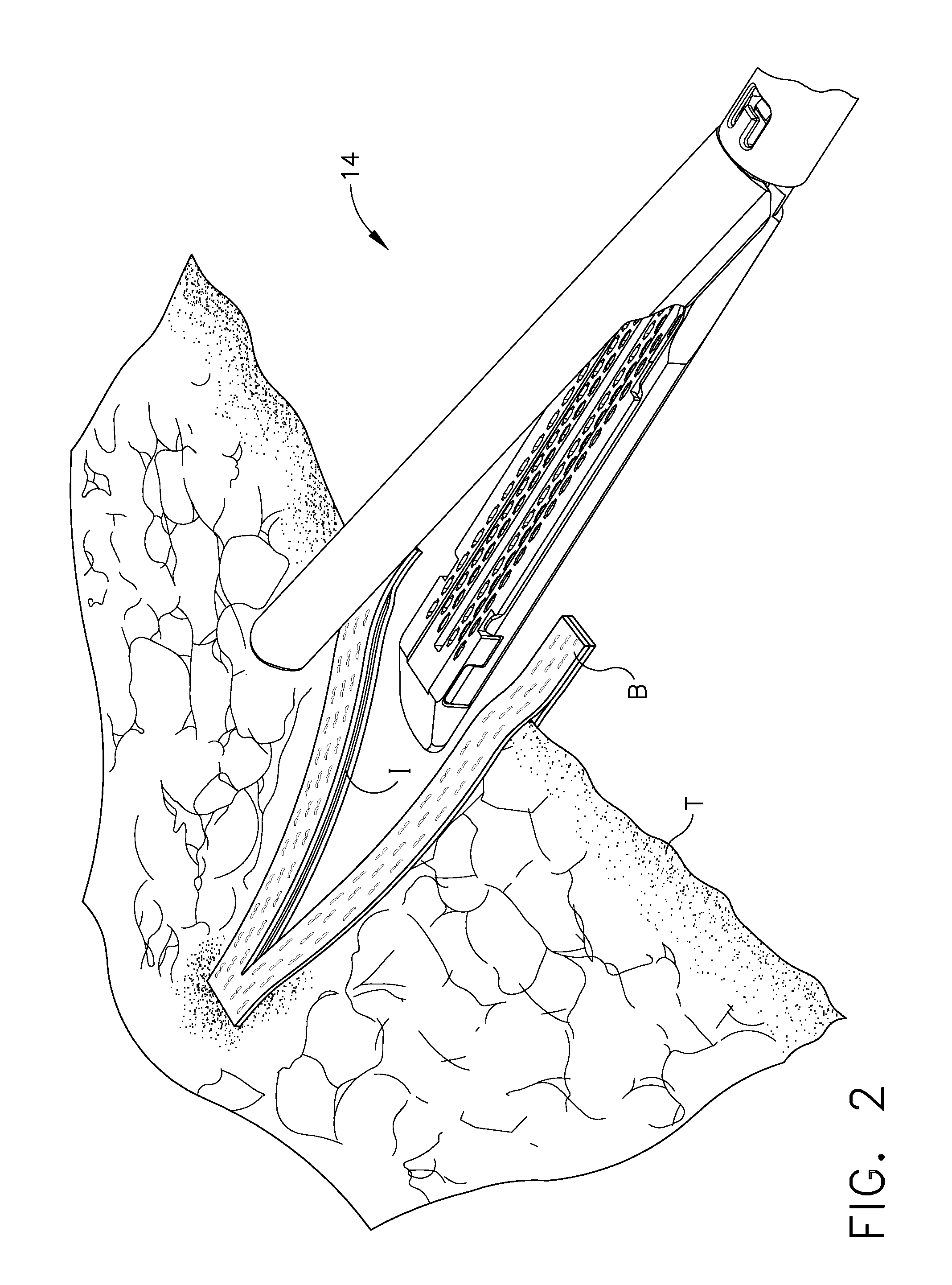
[0078]In various embodiments, referring to FIGS. 1-2, an end-effector of a surgical instrument can include at least one piece of buttress material “B” releasably a...


PUM

PropertyMeasurementUnit
perimeteraaaaaaaaaa
bioabsorbableaaaaaaaaaa
compressive forceaaaaaaaaaa

Abstract

A piece of buttress material and an end-effector of a surgical instrument including features which can aid a surgeon in properly and quickly attaching the piece of buttress material to the end-effector. In various embodiments, a piece of buttress material can include retention features which can be engaged with portions of an end-effector to releasably retain the piece of buttress material to at least a portion of the end-effector. Similarly, an end-effector can include features configured to engage portions of a piece of buttress material to releasably retain the piece of buttress material to the end-effector. In at least one embodiment, more than one piece of buttress material can be releasably retained to an end-effector.

Description

BACKGROUND[0001]i. Field of the Invention[0002]The present invention generally relates to buttress material for a surgical instrument, and to buttress material configured to be releasably attached to an end-effector assembly of a surgical instrument.[0003]ii. Description of the Related Art[0004]A surgical instrument, such as a surgical stapler, for example, can be configured to deploy staples into tissue during a surgical procedure. In various embodiments, the surgical stapler can include an end-effector configured to be positioned on a distal end of the surgical stapler. The end-effector can be configured to be positioned within, and slid at least partially through, a cannula, or trocar, positioned in a wall of a patient's body such that a surgeon can utilize the end-effector to perform work within a surgical site. In various embodiments, the end-effector can comprise a first jaw member including a staple cartridge and, additionally, a second jaw member including an anvil. The firs...

Claims


Application Information

Patent Timeline
Patent Type & Authority Patents(United States)
IPC IPC(8): A61B17/072
CPCA61B17/07207A61B19/026A61B17/07292A61B17/32A61B2017/00477A61B2017/005A61B2017/07214A61B2017/07242A61B2017/0725A61B2017/07285A61B2019/0267A61B2017/00951A61B2050/002A61B2017/00495A61B50/30A61B2050/314
Inventor HUITEMA, THOMAS W.SHELTON, IV, FREDERICK E.SWAYZE, JEFFREY S.MORGAN, JEROME R.
Owner CILAG GMBH INT
Why Eureka
Try Eureka