Supercharge Your Innovation With Domain-Expert AI Agents!

Stackable capacitor structure

a capacitor and stacking technology, applied in the field of stackable capacitor structure, can solve the problem of difficult choice of the number and parameter of each capacitor

Inactive Publication Date: 2013-02-12
HON HAI PRECISION IND CO LTD
View PDF2 Cites 0 Cited by
  • Summary
  • Abstract
  • Description
  • Claims
  • Application Information

AI Technical Summary

Benefits of technology

Enables flexible and efficient capacitance adjustment without requiring circuit board redesign, effectively managing electromagnetic interference and simplifying the integration of capacitors with varying capacitance values.

Problems solved by technology

As the electromagnetic interference of the other electronic elements, the number and parameter of each capacitor are hard to choose.

Method used


Image

  • Stackable capacitor structure
  • Stackable capacitor structure
  • Stackable capacitor structure

Examples


Embodiment Construction

[0009]Embodiments of the disclosure will now be described in detail, with reference to the accompanying drawings.

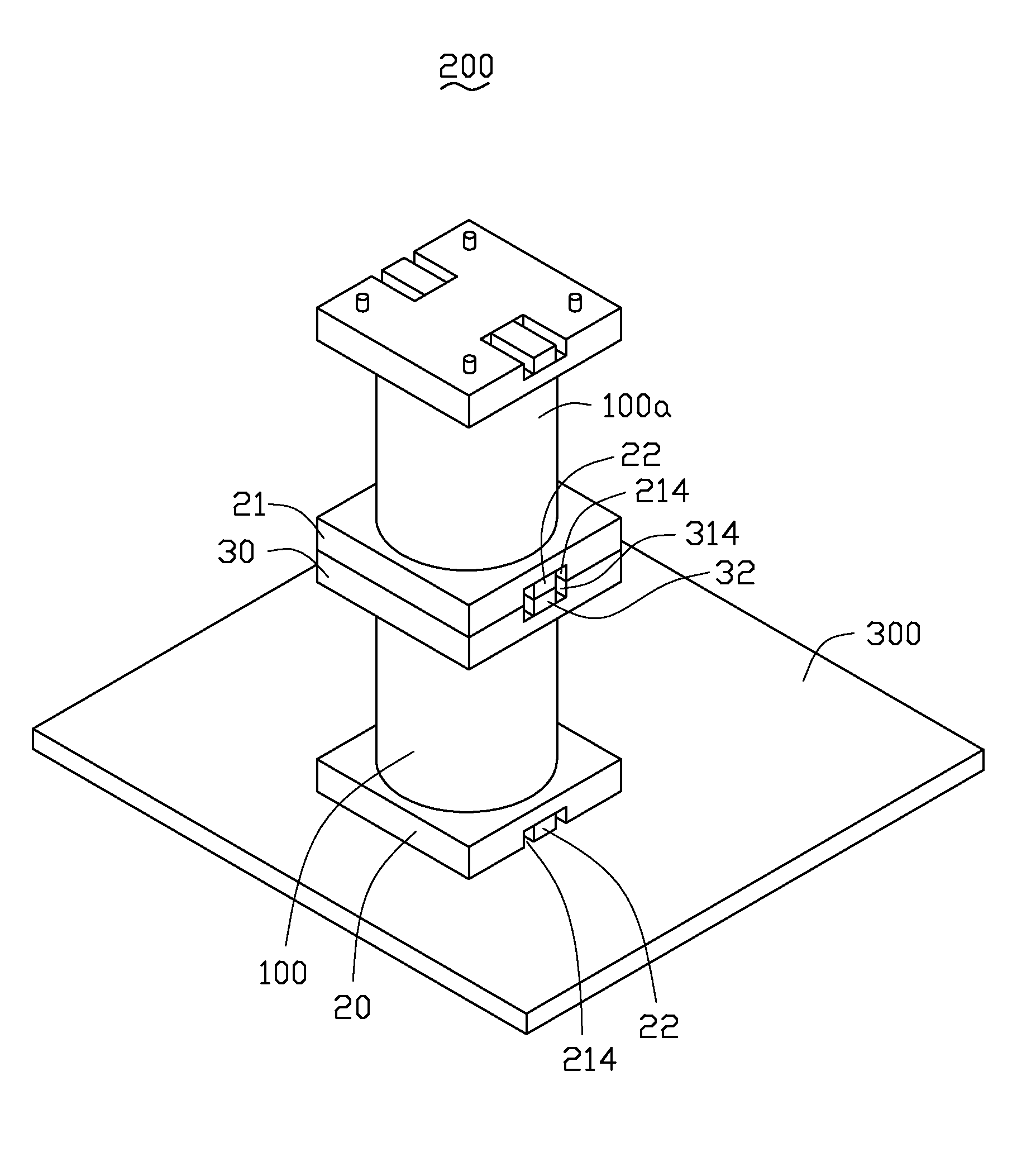
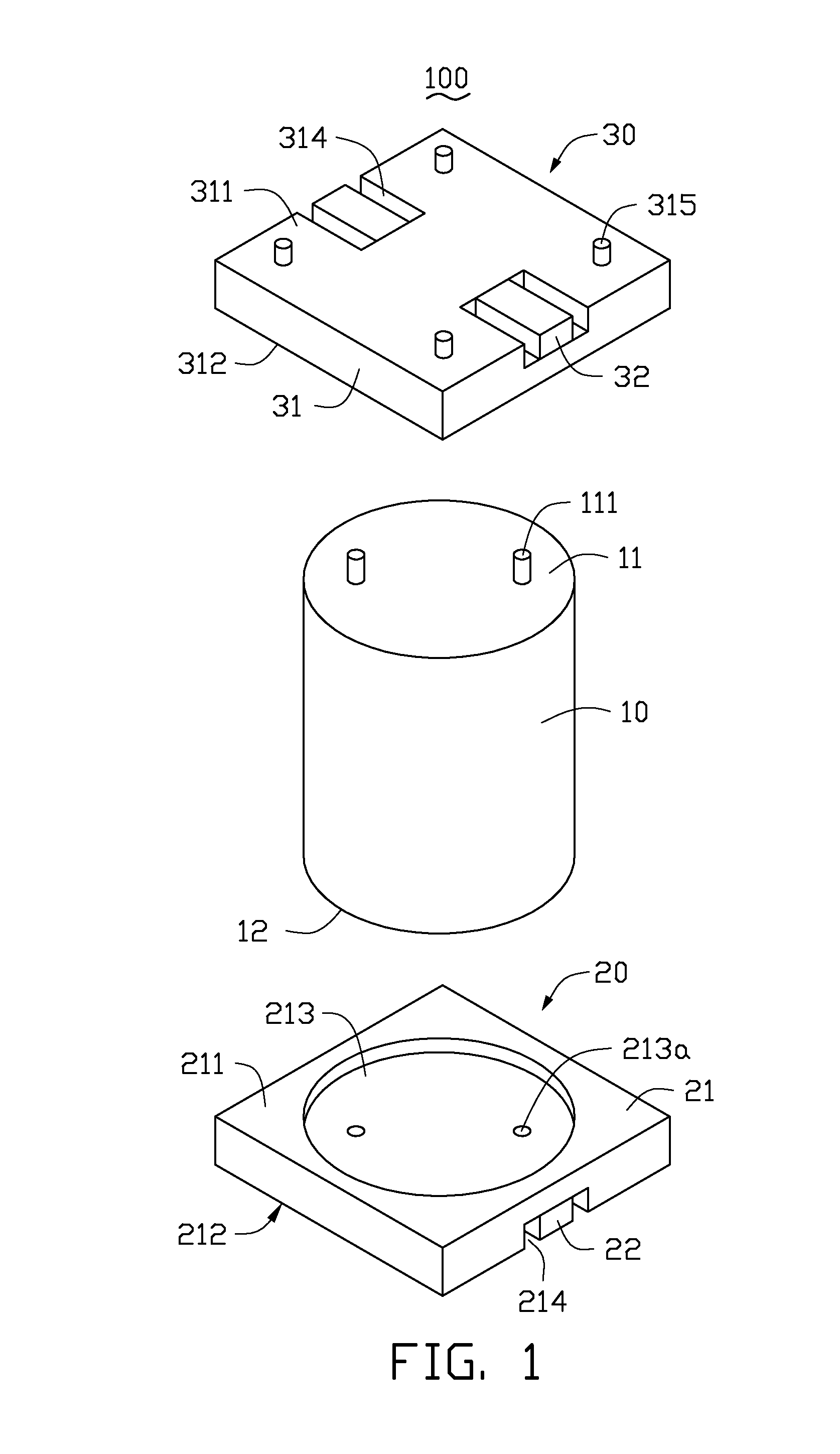
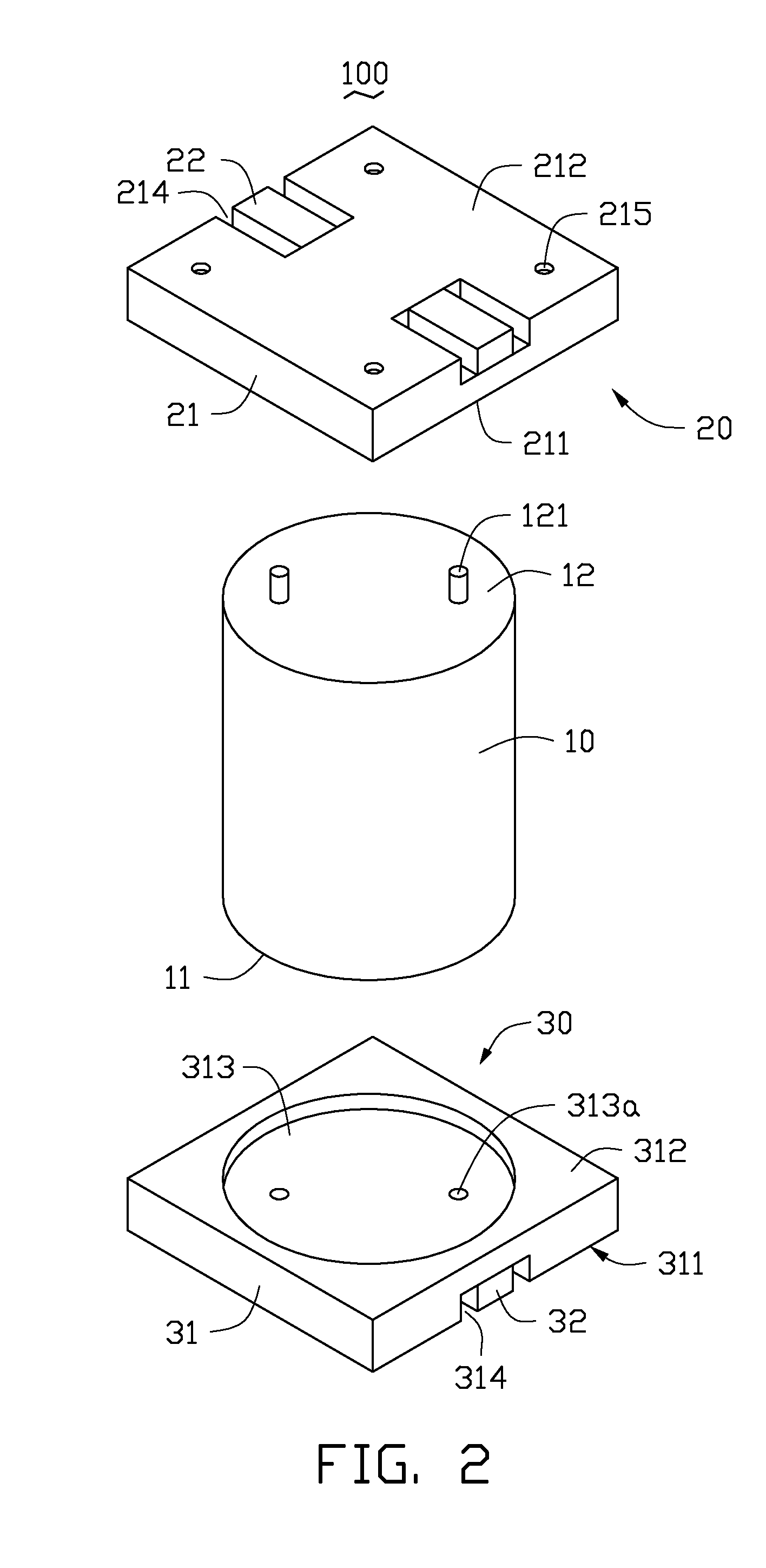
[0010]Referring to FIGS. 1-2, a capacitor 100, according to an exemplary embodiment, includes a main body 10, a first seat 20, and a second seat 30.

[0011]The main body 10 is cylindrical shaped, and includes a first end surface 11 and a second end surface 12 opposite to the first end surface 11. Two first pins 111 extend upward from the first end surface 11, and two second pins 121 extend downward from the second end surface 12. The first pins 111 electrically connect to the second pins 121 via inner structures of the main body 10.

[0012]The first seat 20 is rectangular shaped, and includes a first substrate 21 and two first pads 22 positioned on the first substrate 21. The first substrate 21 includes a first upper surface 211 and a first lower surface 212 opposite to the first upper surface 211. The first substrate 21 defines a first receiving hollow 213 in the middle of t...


PUM

PropertyMeasurementUnit
widthaaaaaaaaaa
capacitanceaaaaaaaaaa
diameteraaaaaaaaaa

Abstract

A capacitor includes a main body, a first seat, and a second seat. The main body includes a first end surface and a second end surface opposite to the first end surface. Two first pins extend upward from the first end surface. Two second pins extend downward from the second end surface. The first pins electrically connect the second pins. The first seat includes a first substrate and two first pads, the first seat is positioned on the second end surface of the main body and the first pads are electrically connected to the second pins. The second seat includes a second substrate and two second pads, the second seat is positioned on the first end surface of the main body and the second pads are electrically connected to the first pins.

Description

BACKGROUND[0001]1. Technical Field[0002]The present disclosure relates to capacitors, and particularly, to a stackable capacitor structure.[0003]2. Description of Related Art[0004]Capacitors are typically used in circuits, and include a main body and a metal pad positioned at the bottom of the main body. The capacitors are mounted on a circuit board via the metal pads. As the electromagnetic interference of the other electronic elements, the number and parameter of each capacitor are hard to choose. When a small capacitor with low capacitance must be changed to a big capacitor with high capacitance, the circuit board needs to be redesigned for the big capacitor.[0005]Therefore, it is desirable to provide a stackable capacitor structure which can overcome the limitations described.BRIEF DESCRIPTION OF THE DRAWINGS[0006]FIG. 1 is an isometric and exploded view of a capacitor in accordance with an exemplary embodiment.[0007]FIG. 2 is similar to FIG. 1, but viewed from another angle.[00...

Claims


Application Information

Patent Timeline
Patent Type & Authority Patents(United States)
IPC IPC(8): H01G9/04H01G4/38H01M8/24H01M6/42H01M2/20
CPCH01G4/30H01G4/38H01G9/14H01G11/12H01G2/06H05K1/181Y02E60/13H05K3/301H05K2201/10015H05K2201/10515H05K2203/167Y02P70/50
Inventor LAI, CHUN-AN
Owner HON HAI PRECISION IND CO LTD
Features
  • R&D
  • Intellectual Property
  • Life Sciences
  • Materials
  • Tech Scout
  • Unparalleled Data Quality
  • Higher Quality Content
  • 60% Fewer Hallucinations
Learn More