
Rowing boat footrest assembly

a footrest and rowing boat technology, applied in the field of rowing boat footrest assembly, can solve the problems of difficulty for rowers to operate the rudder while rowing

Inactive Publication Date: 2013-02-19
SHIMANO INC
View PDF8 Cites 0 Cited by
  • Summary
  • Abstract
  • Description
  • Claims
  • Application Information

AI Technical Summary

Benefits of technology

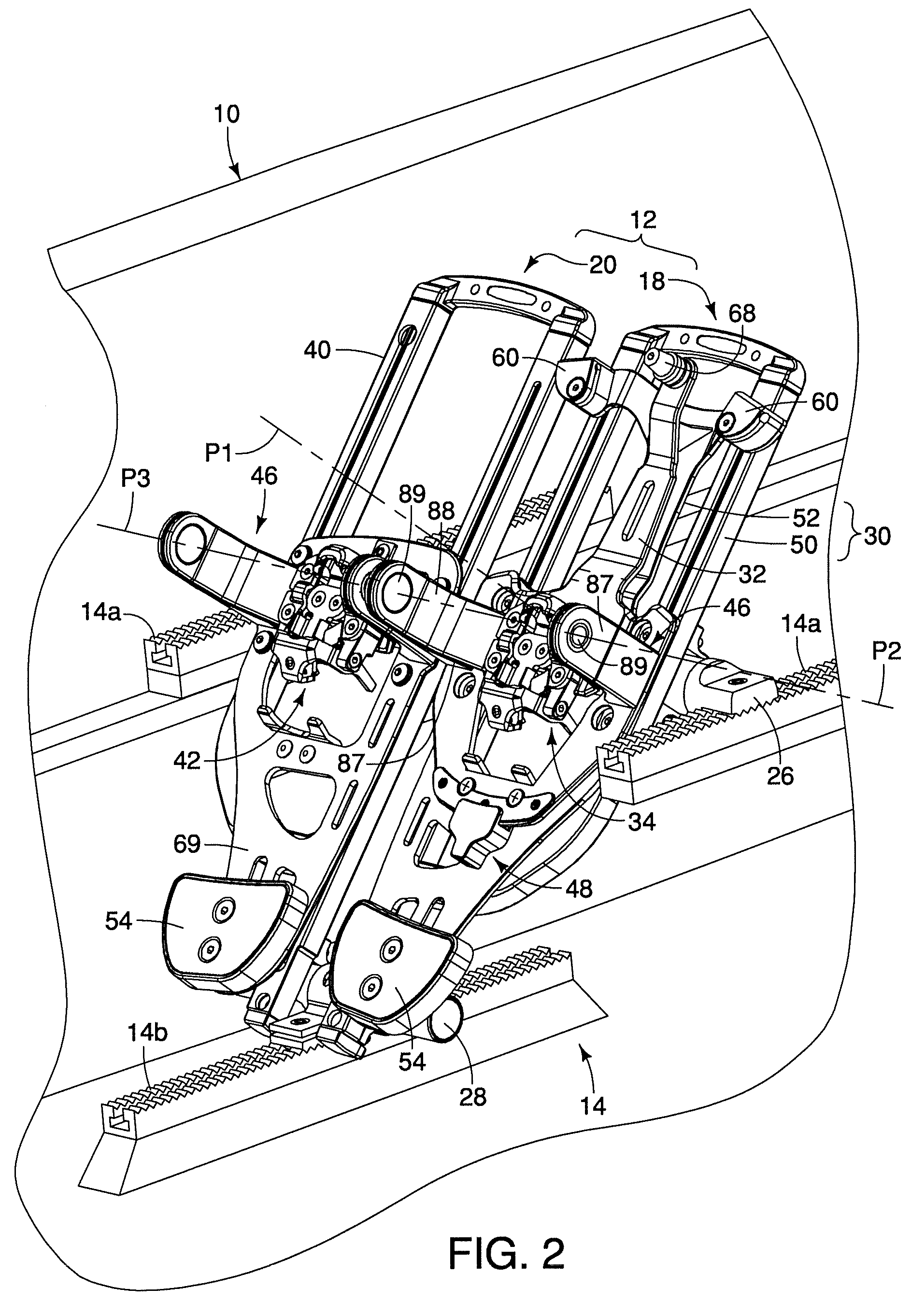
The present invention provides a rowing boat footrest assembly that includes a rudder control function. It includes a base, a foot-rudder control member, a footrest member, and two pivot structures. The foot-rudder control member has a rudder control attachment, and the footrest member has a shoe attachment. The first pivot structure pivotally supports the foot-rudder control member on the base, while the second pivot structure pivotally supports the footrest member on the first pivot structure to change the shoe inclination of the footrest member with respect to the foot-rudder control member. The second pivot axis is not parallel to the first pivot axis. This design allows the user to easily control the rudder and change the shoe inclination with one footrest assembly.

Problems solved by technology

Since a rower is typically using both hands for rowing, it is difficult for the rower to operate the rudder while rowing.

Method used


Image

  • Rowing boat footrest assembly
  • Rowing boat footrest assembly
  • Rowing boat footrest assembly

Examples


Embodiment Construction

[0036]Selected embodiments will now be explained with reference to the drawings. It will be apparent to those skilled in the art from this disclosure that the following descriptions of the embodiments are provided for illustration only and not for the purpose of limiting the invention as defined by the appended claims and their equivalents.

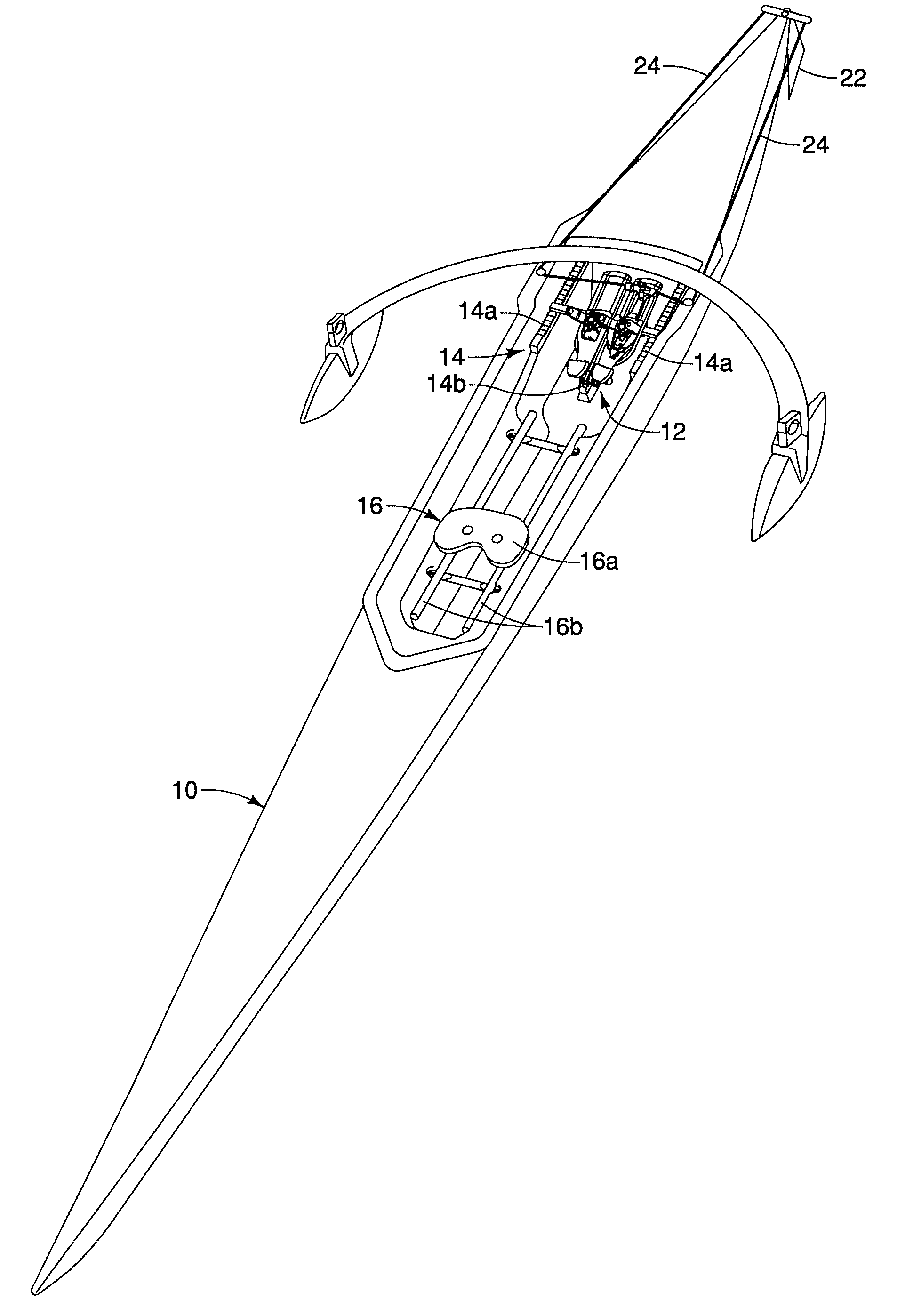
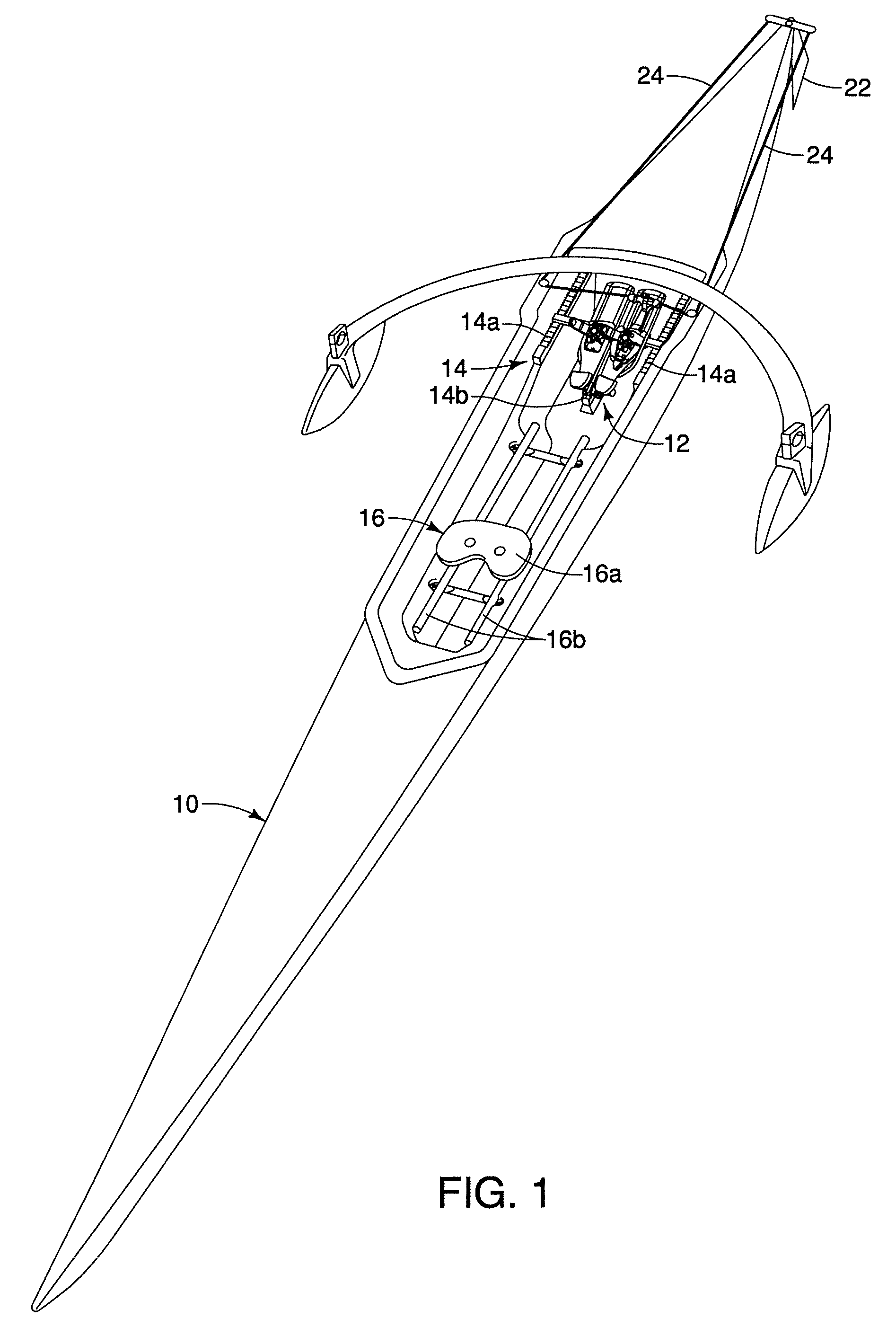
[0037]Referring initially to FIG. 1, a rowing boat 10 is illustrated that is equipped with a rowing boat footrest assembly 12 in accordance with a first embodiment. In this illustrated embodiment, the rowing boat 10 includes a stationary boat mounting structure 14 for supporting the rowing boat footrest assembly 12, and a sculling seat structure 16. While the rowing boat footrest assembly 12 is installed in a single person rowing boat in this illustrated embodiment, typically the boat footrest assembly 12 is installed in boats for two or more rowers such that one of the rowers can steer the boat with the boat footrest assembly 12. Thus, the boat f...


PUM


Abstract

A rowing boat footrest assembly is provided with a base, a foot-rudder control member, a footrest member, a first pivot structure and a second pivot structure. The foot-rudder control member includes a rudder control attachment. The footrest member includes a shoe attachment. The first pivot structure pivotally supports the foot-rudder control member on the base. The first pivot structure defines a first pivot axis of pivotal movement between the foot-rudder control member and the base. The second pivot structure pivotally supports the footrest member on the foot-rudder control member to change a shoe inclination of the footrest member with respect to the foot-rudder control member. The second pivot structure defines a second pivot axis of pivotal movement between the footrest member and the foot-rudder control member. The second pivot axis is not parallel to the first pivot axis.

Description

BACKGROUND[0001]1. Field of the Invention[0002]This invention generally relates to a rowing boat footrest assembly. More specifically, the present invention relates to a rowing boat footrest assembly which includes a rudder control function.[0003]2. Background Information[0004]Traditionally, the footrest in a rowing boat is an angled surface upon which a rower can brace his or her feet to provide increased power during the rowing process. Recently, footrests have been provided with simple shoe retaining straps or mechanisms that hold a rower's shoe against the surface of the footrest. Typically, the footrest cannot move during the rowing back and forth stroke. However, the footrest is often adjustable to accommodate different sizes of rowers. In some instances, the location of the entire footrest is adjustable in the longitudinal direction of the rowing boat. Also, in some cases, the angle of the footrest is adjustable with respect to the rowing boat.[0005]In some cases, rowing boat...

Claims


Application Information

Patent Timeline
Patent Type & Authority Patents(United States)
IPC IPC(8): B63B17/00
CPCB63H16/02B63B35/85B63B2035/734B63B34/30B63H25/36
Inventor SAKAUE, ATSUSHI
Owner SHIMANO INC
Learn More