Liquid crystal display device and driving unit thereof

a technology of liquid crystal display and driving unit, which is applied in the direction of digital storage, optics, instruments, etc., can solve the problems of delay in scan signal pulses, difficulty in ensuring a sufficient time for charging the first node ndb>1/, and difficulty in ensuring a sufficient time for charging the second node ndb>2/b>, etc., to achieve the effect of sufficient charging tim

Active Publication Date: 2013-02-26
LG DISPLAY CO LTD
View PDF5 Cites 1 Cited by
  • Summary
  • Abstract
  • Description
  • Claims
  • Application Information

AI Technical Summary

Benefits of technology

[0029]Therefore, an object of the present invention is to provide a driving unit for a liquid crystal display device in which flip-flops of a shift register unit are divided into two groups and driven so as to ensure a sufficient charging time for each flip-flop, whereby a rising time and a falling time of output signals are reduced to output high potential voltages with desired levels as the output signals.

Problems solved by technology

Therefore, it would be difficult to ensure a sufficient time for charging the first Node ND1.
That is, pulses of the scan signals fall with delay.
Similarly, when the horizontal period is reduced, it is difficult to ensure a sufficient time taken by charging the second Node ND2.
As a result, the eighth transistor T8 is not completely turned on, which causes limitation on electric charge which is discharged through the eighth transistor T8, thereby taking a longer time period (falling time) to lower the potential levels of the scan signals.
Furthermore, resistance and capacitance elements of the increased gate lines increase a load in the shift register unit to lengthen the rising time and the falling time of the scan signals.
Especially, in the driving circuit-integrated LCD panel applying amorphous silicon transistor thereto, due to its lower electron mobility, the rising time and the falling time of the scan signals may be longer.
Moreover, when the rising time or the falling time of the scan signals is lengthened, waveforms of the scan signals fall with delay to maintain high potential levels for a long time, thereby unnecessarily turning on TFTs.
This may cause degradation of image quality.
In addition, when the waveforms of the scan signals fall with delay, the time period for outputting the scan signals have to be further reduced to prevent adjacent scan signals from being overlapped with one another, which makes it difficult to fabricate a LCD device with high resolution.

Method used


Image

  • Liquid crystal display device and driving unit thereof
  • Liquid crystal display device and driving unit thereof
  • Liquid crystal display device and driving unit thereof

Examples


Embodiment Construction

[0042]Reference will now be made in detail to the preferred embodiments of the present invention, examples of which are illustrated in the accompanying drawings.

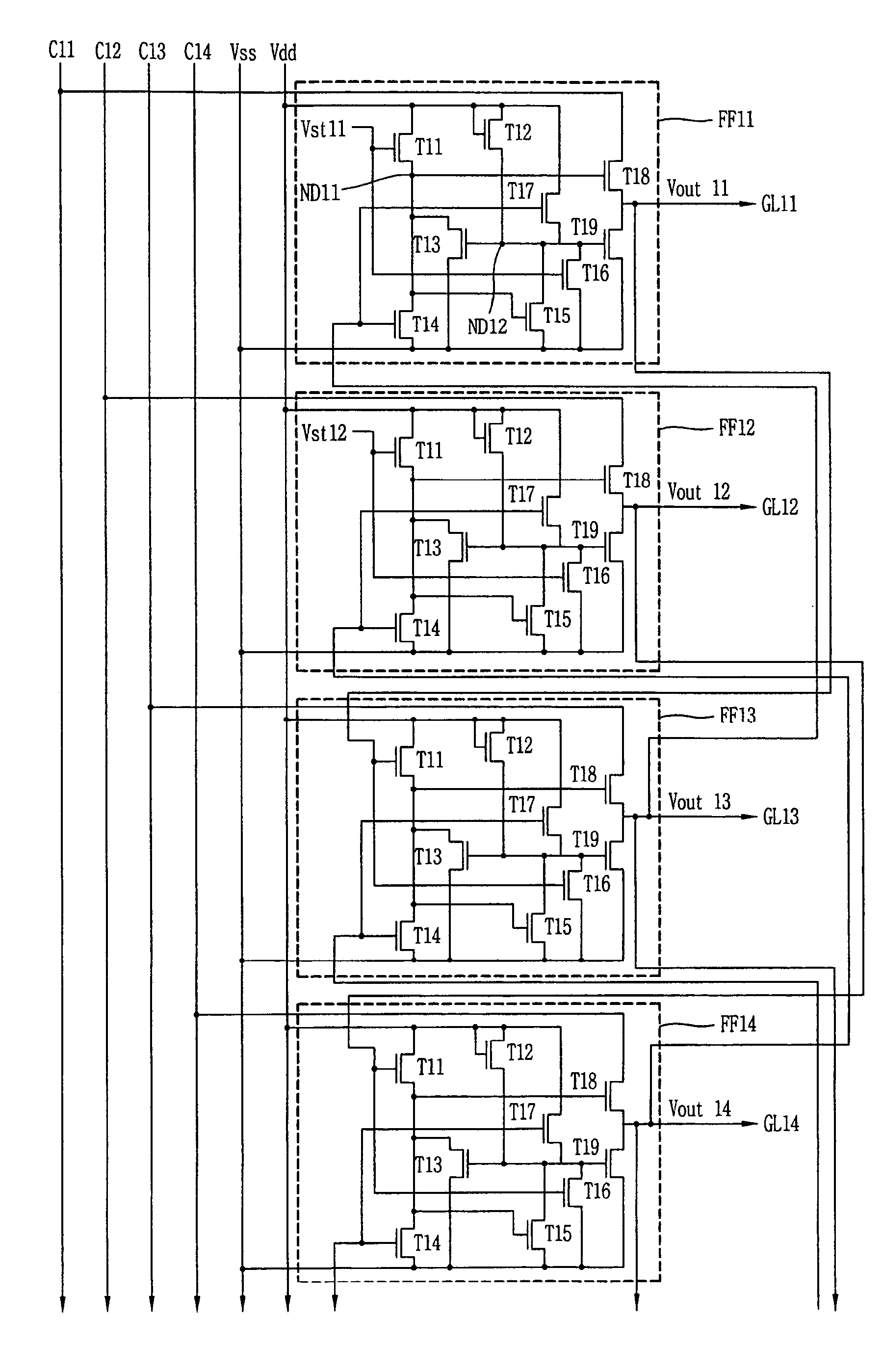
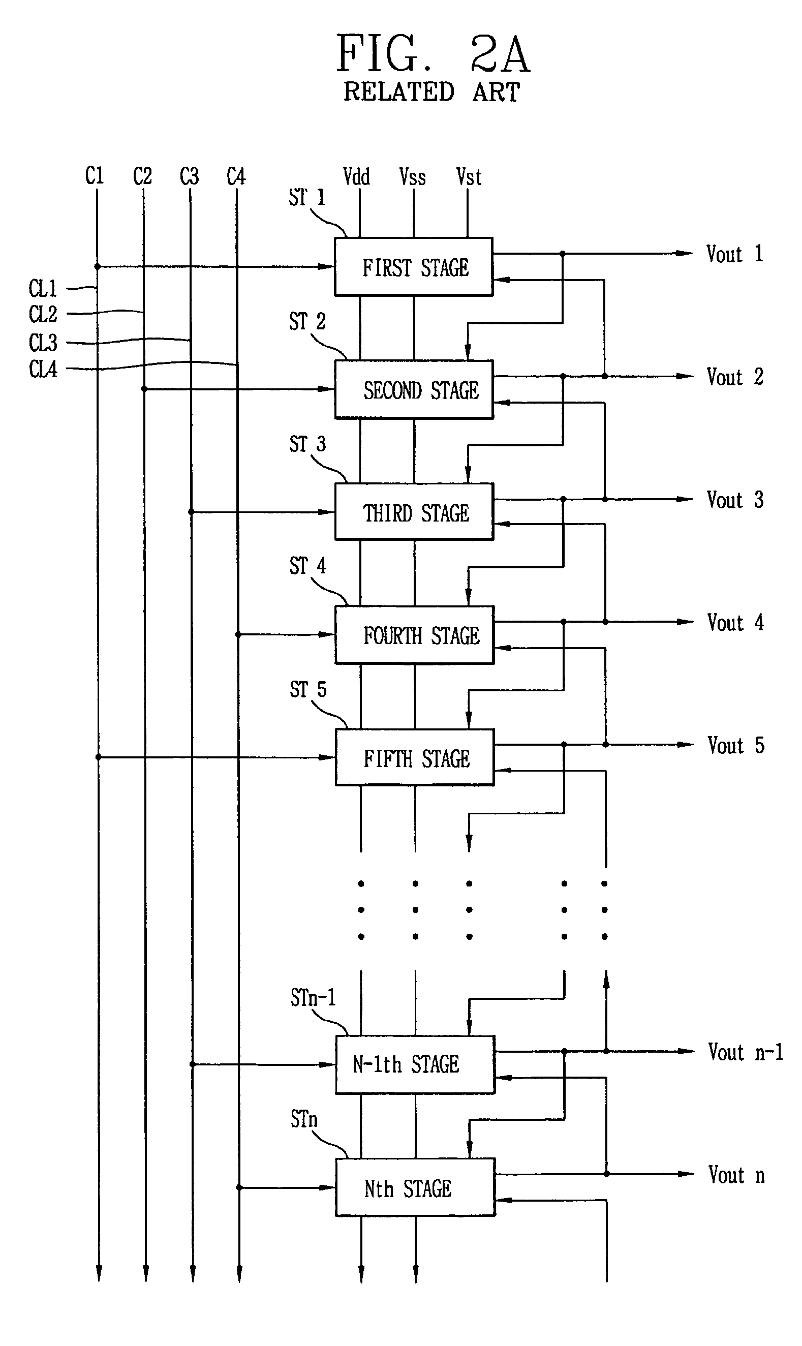
[0043]To achieve objects of the present invention, a driving unit for a liquid crystal display (LCD) device of an embodiment of the present invention includes: a first group of stages initially set by a first gate start voltage and synchronized with clock signals, for sequentially applying scan signals to the gate lines, and a second group of stages initially set by a second gate start voltage and synchronized with clock signals, for sequentially applying output signals to the gate lines. Each Nth stage of the first and second groups is set by output signals of each N−1th stage (i.e., the next subsequent stage of the first or second group) thereof. An output of each N−1th stage of the first and second groups is stopped by output signals of each Nth stage of the first and second groups. In addition, output signals of the stag...


PUM


Abstract

A driving unit for a liquid crystal display device is provided. The driving unit includes a first group of driving stages and a second group of driving stages. A first driving stage of the first group receives a first gate start voltage. The first group of driving stages sequentially outputs scan signals according to a first clock signal. The scan signal outputted by one driving stage of the first group is sent to a next subsequent driving stage of the first group. A first driving stage of the second group receives a second start voltage. The second group of driving stages sequentially outputs the scan signals according to a second clock signal. The scan signal outputted by one driving stage of the second group is sent to a next subsequent driving stage of the second group. The driving stages of the first group and the second group alternately output the scan signals.

Description

[0001]This Nonprovisional application claims priority under 35 U.S.C. §119(a) on Patent Application No. 10-2004-0118470 filed in Korea on Dec. 31, 2004, the entire contents of which are hereby incorporated by reference.BACKGROUND OF THE INVENTION[0002]1. Field of the Invention[0003]The present invention relates to a liquid crystal display (LCD) device and a driving unit thereof, and particularly, to a liquid crystal display (LCD) device and driving unit capable of facilitating application of high resolution and improving image quality.[0004]2. Description of the Background Art[0005]Recently, since information was visually embodied, display devices which act as an interface between human being and information have been widely utilized. More particularly, because of the superior characteristics of liquid crystal display (LCD) devices such as clear image quality, low power consumption, light weight and the like, the LCD devices have been gradually utilized as a next-generation display ...

Claims


Application Information

Patent Timeline
Patent Type & Authority Patents(United States)
IPC IPC(8): G09G3/36
CPCG09G3/3677G11C19/28G02F1/133
Inventor CHO, HYUNG NYUCKYOON, SOO YOUNGCHUN, MIN DOO
Owner LG DISPLAY CO LTD
Why Eureka
Try Eureka