
Plasma display panel with energy recovery circuit and driving method thereof

a technology of energy recovery circuit and display panel, which is applied in the field of plasma display panel, can solve the problems of inability to recover all of the energy, hard-switching of the switching elements, and inability to increase voltage, so as to reduce the number of switching elements, increase the terminal voltage of the panel capacitor, and reduce the rising and falling time of the panel voltage.

Inactive Publication Date: 2008-01-29
SAMSUNG SDI CO LTD
View PDF26 Cites 1 Cited by
  • Summary
  • Abstract
  • Description
  • Claims
  • Application Information

AI Technical Summary

Benefits of technology

The present invention relates to a plasma display panel and a driving apparatus for it. The technical effects of the invention include reducing the rising and falling time of the panel voltage, reducing the number of switching elements, and increasing the energy recovery efficiency. The energy recovery circuit stores energy in the inductor and uses it to alter the terminal voltage of the panel capacitor. The driving apparatus includes an inductor, a panel capacitor, and switching elements to form current paths for storing and using energy. The method of driving the plasma display panel involves turning on and off the switching elements to alter the terminal voltage and maintain it at a desired level.

Problems solved by technology

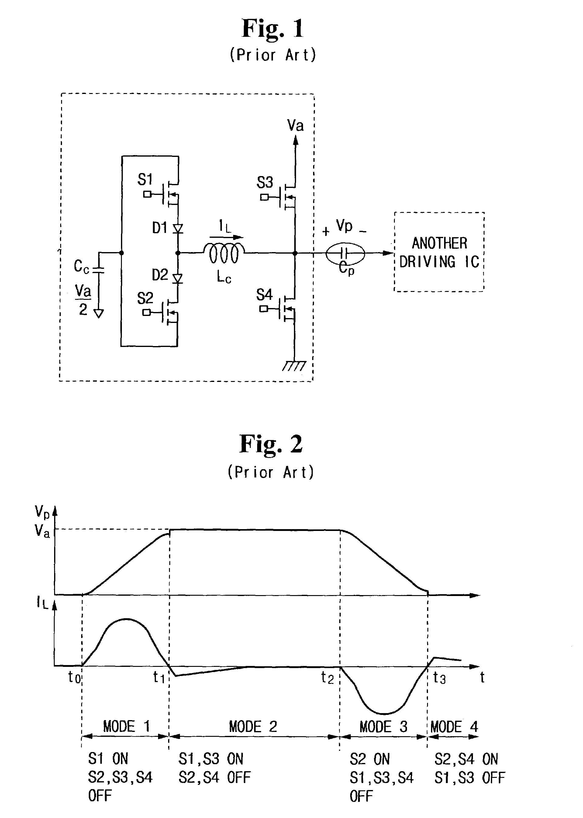
In the conventional energy recovery circuit configured as above, however, there is a problem that all of the energy is not recovered due to loss of the circuit itself such as ON loss of the switching elements or the switching loss.
Thereby, the address voltage cannot be increased to a desired voltage Va or cannot be decreased to a ground voltage, and this causes a hard-switching of the switching elements.
In addition, a rising time and a falling time of the address voltage become longer, and this causes the addressing speed to be lower.

Method used


Image

  • Plasma display panel with energy recovery circuit and driving method thereof
  • Plasma display panel with energy recovery circuit and driving method thereof
  • Plasma display panel with energy recovery circuit and driving method thereof

Examples


Embodiment Construction

[0041]In the drawings, the parts with no relation to the description will be omitted for clarity. Like numerals refer to like elements throughout. It will be understood by those skilled in the art that when an element is referred to as “connection with” another element, it can be directly connected with the other element or intervening elements may also be present electrically.

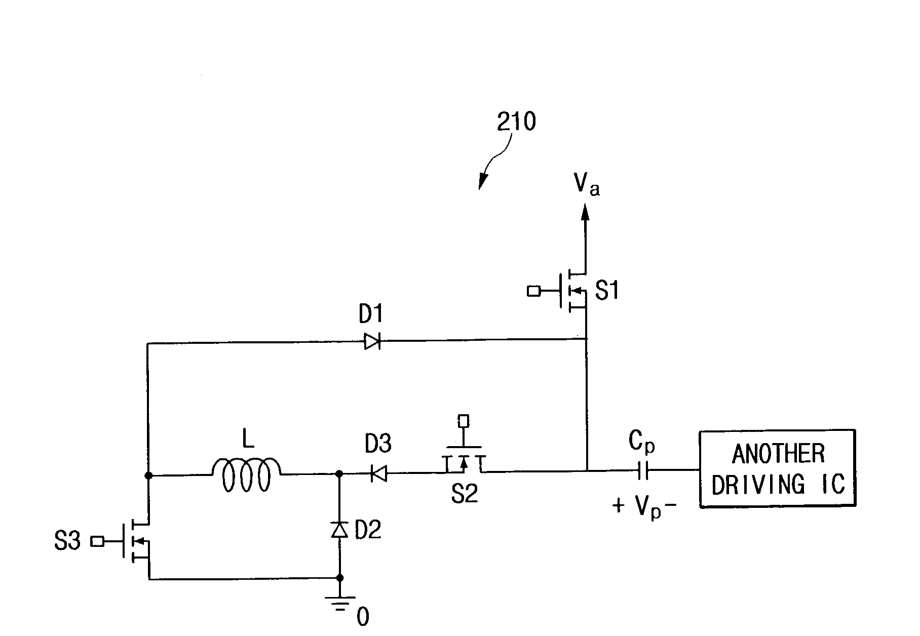
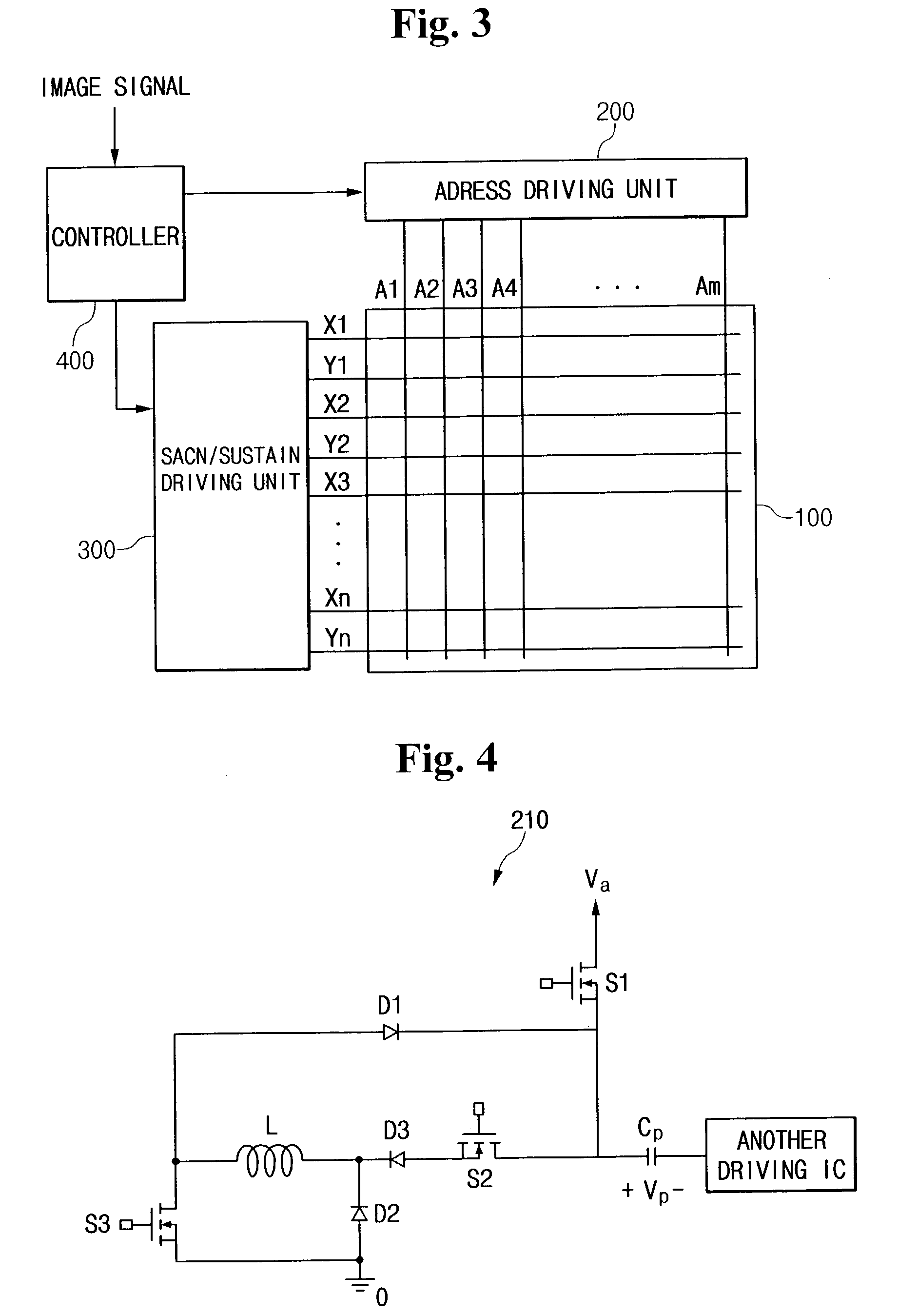
[0042]First, referring to FIG. 3, the plasma display panel according to an embodiment of the present invention will be described. As shown in FIG. 3, the plasma display panel includes plasma panel 100, address driving unit 200, scan / sustain driving unit 300, and controller 400.

[0043]Plasma panel 100 includes a plurality of address electrodes A1 to Am disposed in a longitudinal direction, and a plurality of scan electrodes Y1 to Yn and a plurality of sustain electrodes X1 to Xn alternately disposed in a transverse direction. X electrodes X1 to Xn are formed corresponding to Y electrodes Y1 to Yn, and typically,...


PUM


Abstract

A plasma display panel with a driving apparatus including an inductor of which one end is electrically connected to one end of a panel capacitor. The driving apparatus of the plasma display panel alters a terminal voltage of the panel capacitors into a second voltage by storing energy in the inductor using energy of the panel capacitor charged with a first voltage. The terminal voltage of the panel capacitor is changed into the second voltage, and thereafter, it is maintained at the second voltage by freewheeling current flowing through the inductor. In addition, the terminal voltage of the panel capacitor is changed into the first voltage using the energy stored in the inductor. The terminal voltage of the panel capacitor is maintained at the first voltage by connecting one end of the panel capacitor to a first voltage source after it is changed into the first voltage.

Description

CROSS-REFERENCE TO RELATED APPLICATIONS[0001]This application claims priority to and the benefit of Korean Application No. 2002-0011647, filed on Mar. 5, 2002 in the Korean Intellectual Property Office, the entire disclosure of which is incorporated herein by reference.BACKGROUND OF THE INVENTION[0002](a) Field of the Invention[0003]The present invention relates to a plasma display panel (“PDP”) and a driving method thereof, and more particularly to an energy recovery circuit and a method for driving the same that directly contribute to plasma display discharge.[0004](b) Description of the Related Art[0005]In recent years, flat panel displays such as liquid crystal displays (LCD), field emission displays (FED), PDPs, and the like have been actively developed. The PDP has advantages over the other flat panel displays because of its high luminance, high luminous efficiency, and wide view angle. Accordingly, the PDP is a preferred large-scale screen of larger than 40 inches that can su...

Claims


Application Information

Patent Timeline
Patent Type & Authority Patents(United States)
IPC IPC(8): G09G5/00G09G3/28G09G3/20G09G3/288G09G3/291G09G3/296G09G3/298
CPCG09G3/2965G09G3/296
Inventor LEE, JOO-YUL
Owner SAMSUNG SDI CO LTD
Learn More