Laser power control method and laser power control apparatus

a laser power control and power control technology, applied in the field of laser power control methods and laser power control apparatuses, can solve the problems of hardly performing high-speed recording and hardly performing proper temperature control on recording media

Inactive Publication Date: 2012-07-05
PANASONIC CORP
View PDF4 Cites 2 Cited by
  • Summary
  • Abstract
  • Description
  • Claims
  • Application Information

AI Technical Summary

Benefits of technology

[0017]According to the laser power control method of the present invention, during the user data recording, the bottom driving current is set to the second bottom driving current value that is a current value of a threshold or less, so that the rise time and the fall time of the optical pulse can be shortened to perform the high-speed recording of the optical disk.

Problems solved by technology

When the rise time Tr and the fall time Tf are lengthened, as a result, unfortunately the proper temperature control is hardly performed at the recording medium of the optical disk, and the high-speed recording is hardly performed.

Method used


Image

  • Laser power control method and laser power control apparatus
  • Laser power control method and laser power control apparatus
  • Laser power control method and laser power control apparatus

Examples


first exemplary embodiment

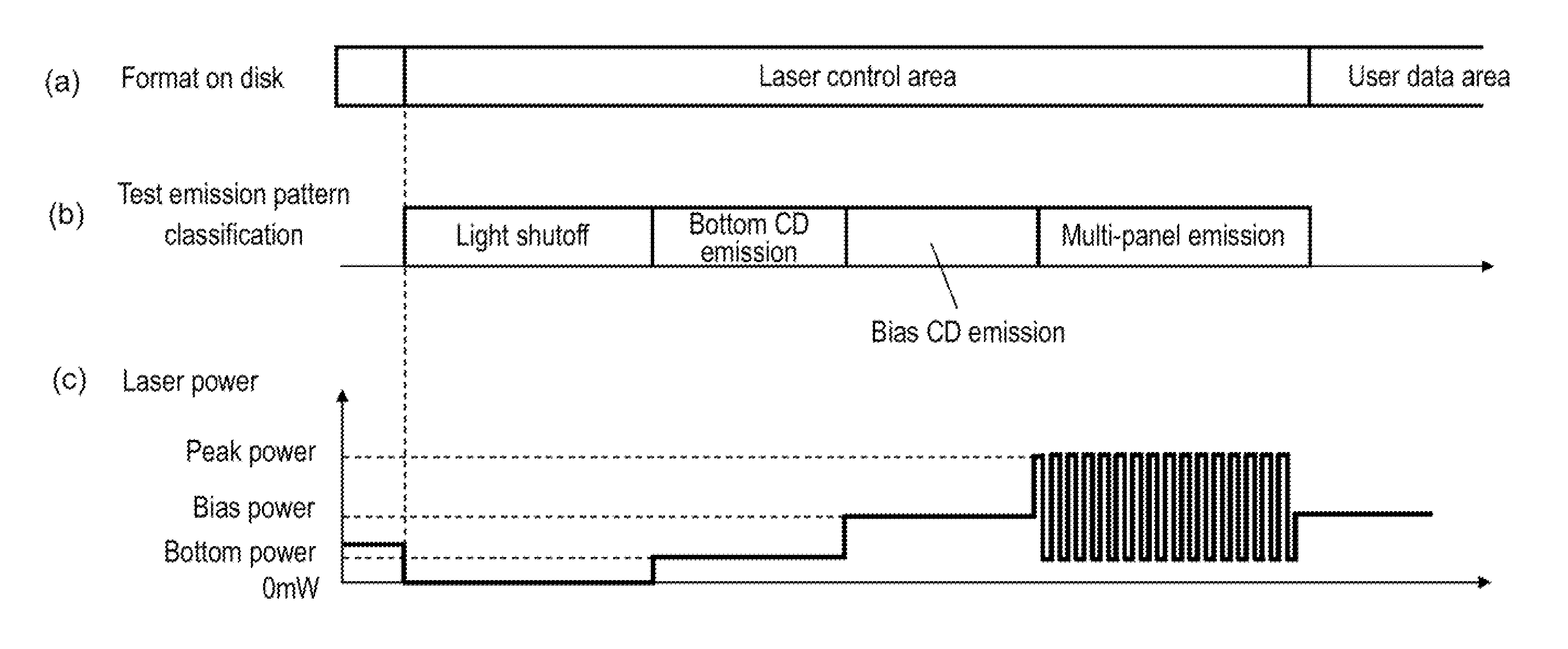
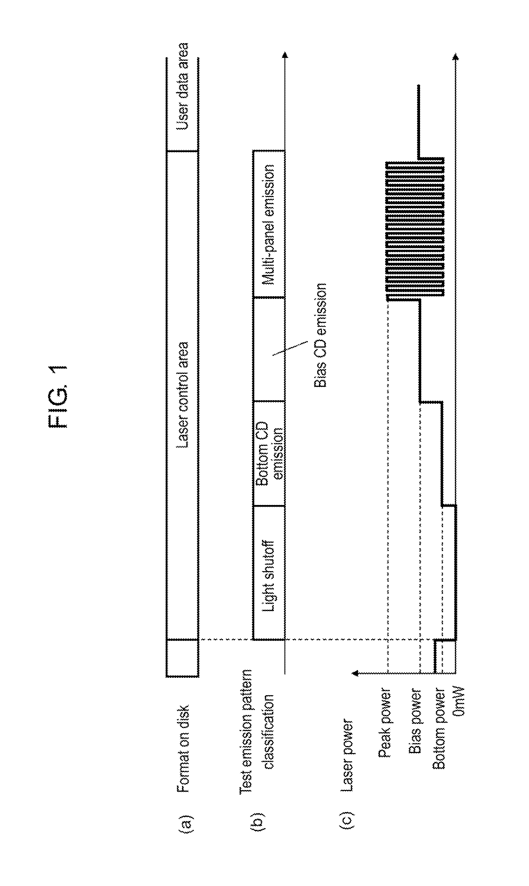
[0038]FIG. 1 is a diagram illustrating an example of a relationship between a test area on an optical disk, which is used in a laser power control method and a laser power control apparatus of the present invention, and a laser power.

[0039]FIG. 1(a) illustrates a laser control area on the optical disk, to which test recording of the laser power is performed and a user data area except the laser control area.

[0040]Test emission of a semiconductor laser is performed in the laser control area that is provided at predetermined intervals on the optical disk, whereby the relationship between the laser power and a driving current is measured to calibrate the laser power. Using the calibrated laser power, the user data is recorded on the optical disk in the user data area subsequent to the laser control area.

[0041]FIG. 1(b) illustrates an example of a test emission pattern in the laser control area. FIG. 1(c) illustrates an example of an emission waveform of the laser. Three kinds of the la...

second exemplary embodiment

[0097]A second exemplary embodiment of the present invention will be described below with a focus on a method for more accurately controlling the optically-modulated waveform.

[0098]FIG. 9 illustrates the optical waveform and a duty of the laser. FIG. 9(a) illustrates the optically-modulated waveform during the conventional multi-pulse recording. The duty of the recording signal is assumed to be about 50%, and the rise time Tr and the fall time Tf are not shortened.

[0099]FIG. 9(b) illustrates the optically-modulated waveform in which the rise time Tr and the fall time Tf are improved to operate at high speed by the first exemplary embodiment of the present invention. In FIG. 9(b), because the bottom driving current is set to the second bottom driving current value Ibm2 that is lower than the threshold Ith, the bottom power becomes approximately 0 mW, and the width of the bottom power is larger than the width of the peak power in the optically-modulated waveform. In other words, the d...


PUM

PropertyMeasurementUnit
bottom poweraaaaaaaaaa
poweraaaaaaaaaa
fall time Tfaaaaaaaaaa

Abstract

With a large capacity of an optical disk and high-speed recording, a frequency of a recording signal is increased and a pulse width is narrowed. In the case that a laser is driven by a signal having the short pulse width, unfortunately the high-speed recording is hardly performed to an optical disk when a rise time and a fall time of the optical pulse are lengthened.
During user data recording, a bottom driving current is set to a second bottom driving current value that is a current value of a threshold or less, so that the rise time and the fall time of the optical pulse can be shortened to perform the high-speed recording of the optical disk.

Description

TECHNICAL FIELD[0001]The present invention relates to a laser power control method and a laser power control apparatus. Particularly, the present invention relates to a laser power control method and a laser power control apparatus, which can perform high-speed recording with a laser beam in an optical disk apparatus that records a signal on an optical disk.BACKGROUND ART[0002]Recently, with a large capacity of an optical disk, a demand for the optical disk is increasing in the fields of an auxiliary storage device of a computer, a consumer video recorder, and the like. With increasing the storage capacity, there is a demand for high-speed recording and high-speed reproduction.[0003]When a recording mark is formed on the optical disk, emission intensity (hereinafter, referred to as a laser power or a power) of a semiconductor laser is set to a plurality of levels and modulated by a recording signal. The plurality of levels depend on a kind of a recording medium of the optical disk. ...

Claims


Application Information

Patent Timeline
Patent Type & Authority Applications(United States)
IPC IPC(8): G11B7/1263G11B7/1267
CPCG11B7/1267G11B7/0062
Inventor FUJIUNE, KENJIYAMAMOTO, TAKEHARU
Owner PANASONIC CORP
Why Eureka
Try Eureka