Switching power supply with plural resonant converters and variable frequency

a technology of resonant converter and power supply, applied in the direction of electric variable regulation, process and machine control, instruments, etc., can solve the problems of increasing the cost of components, increasing the size of single power supply circuit, and reducing the fall time of switching, so as to reduce the cost of components. , the effect of reducing the heat generation of the switching transistor

Inactive Publication Date: 2013-01-08
PANASONIC HEALTHCARE HLDG CO LTD
View PDF17 Cites 12 Cited by
  • Summary
  • Abstract
  • Description
  • Claims
  • Application Information

AI Technical Summary

Benefits of technology

[0023]As has been discussed, according to the present invention, even when power is supplied to a large capacity load, power is applied from a single power supply to the input sides of a plurality of power supply circuits, so that necessary power is sufficiently supplied from the output sides to the large capacity load. Further, a reverse bias voltage is applied to the gate of a switching transistor, so that the fall time of switching is reduced. Moreover, the circuit configuration is simplified while the heat generation of the switching transistor is suppressed to improve the operating efficiency of the overall device, so that the number of circuit components can be greatly reduced.
[0024]Moreover, the control timing of the plurality of power supply circuits is completely synchronized, so that a switching frequency is stably changed and stable power supply can be achieved even in case of fluctuations in input voltage, output voltage, and load current.

Problems solved by technology

However, the resonant switching power supplies of the prior art have problems that will be described below using specific numerical examples.
In this case, the single power supply circuit is naturally increased in size and the cost of components increases.

Method used


Image

  • Switching power supply with plural resonant converters and variable frequency
  • Switching power supply with plural resonant converters and variable frequency
  • Switching power supply with plural resonant converters and variable frequency

Examples


first embodiment

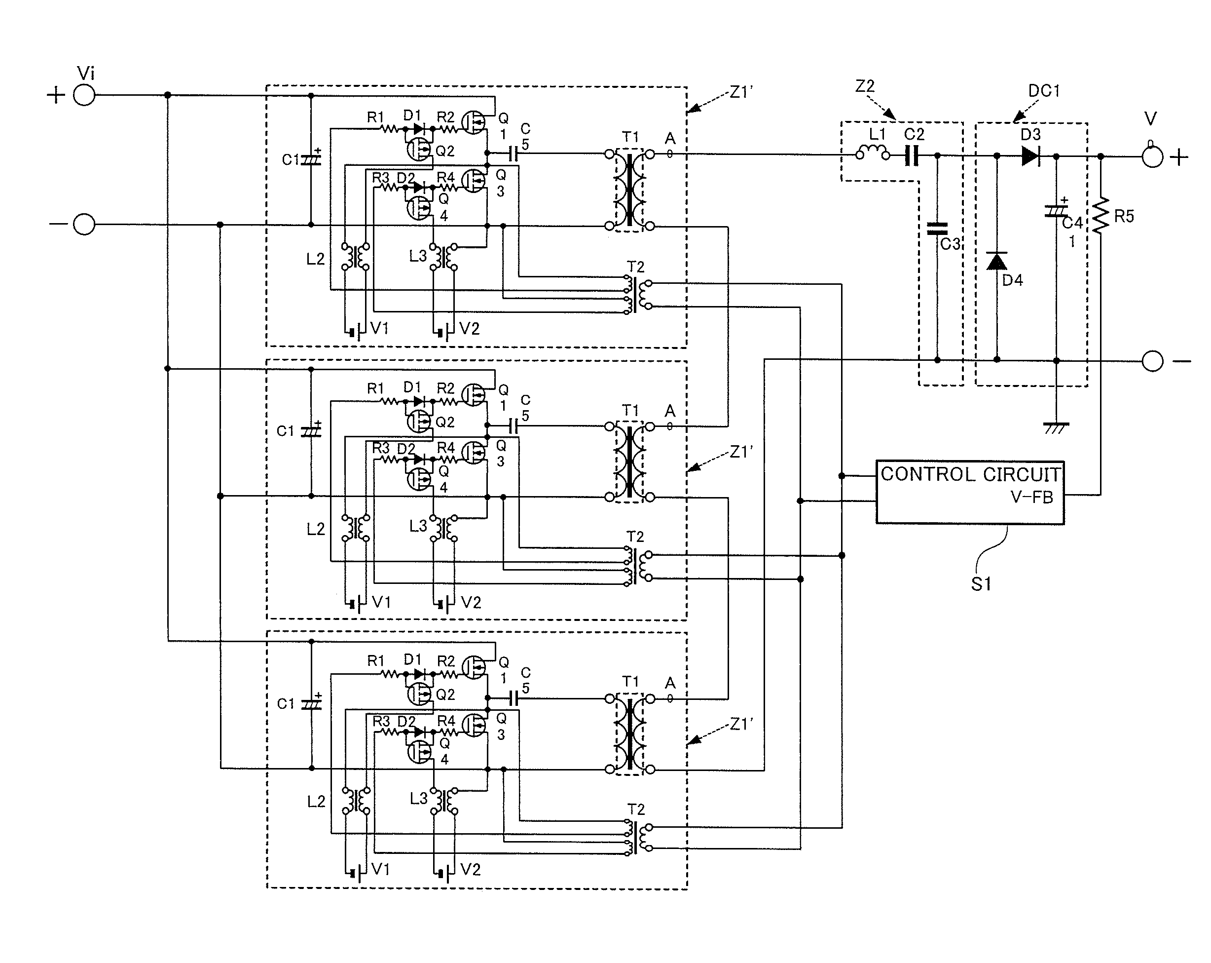
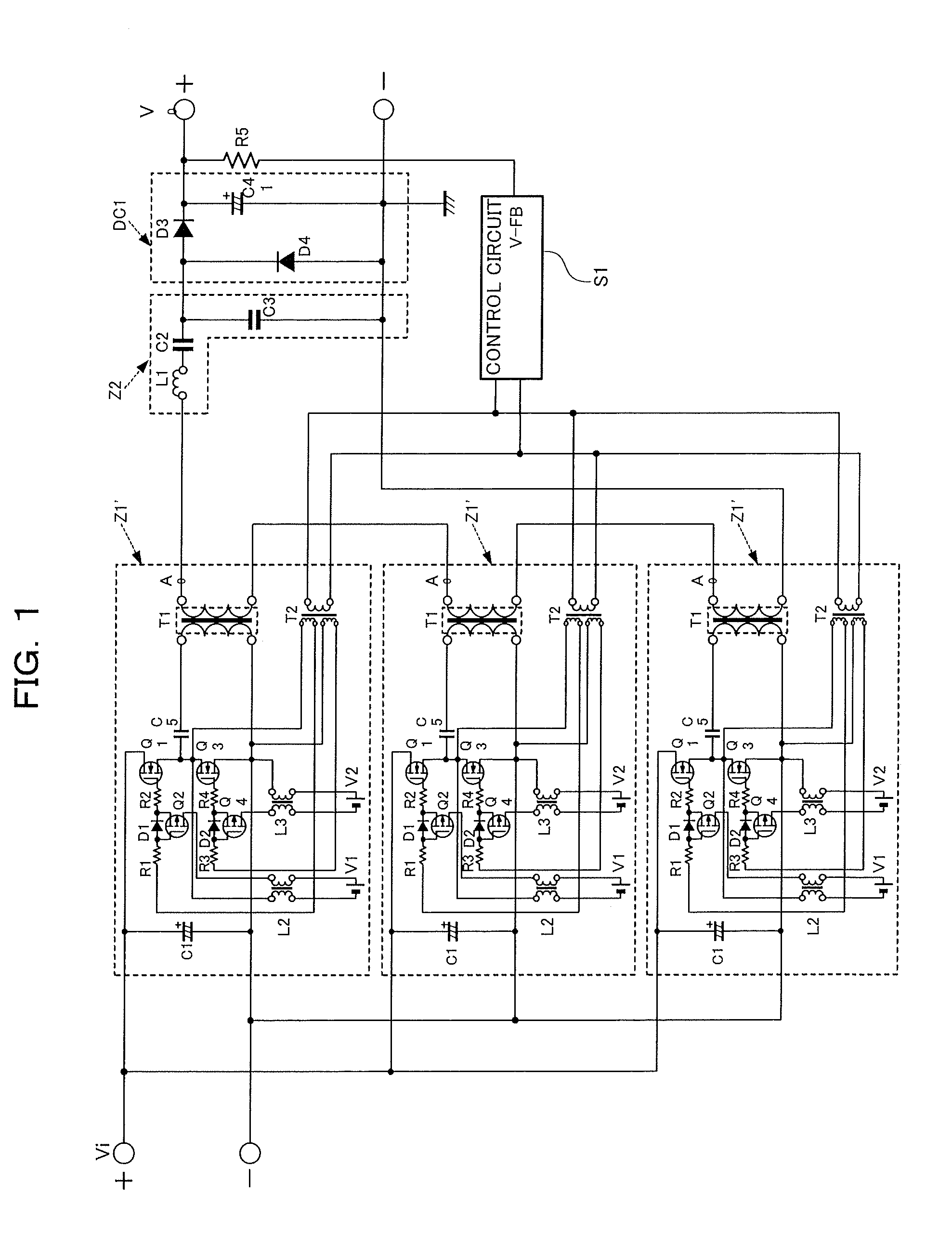
[0033]The following will describe a switching power supply according to a first embodiment of the present invention.

[0034]FIG. 1 is a circuit diagram showing the configuration of a multi serial-parallel resonant switching power supply which is the switching power supply of the first embodiment. In FIG. 1, reference character Vi denotes a direct current input, reference character Ao denotes alternating current outputs, reference character Vo denotes a direct current output, reference character Z1′ denotes power supply circuits, reference character Z2 denotes a resonance circuit, reference character DC1 denotes a rectifying circuit, reference character S1 denotes a control circuit, reference character C1 denotes smoothing capacitors, reference character Q1 denotes switching transistors, reference character Q2 denotes drawing transistors, reference character Q3 denotes switching transistors, reference character Q4 denotes drawing transistors, reference character R1 denotes resistors (O...

second embodiment

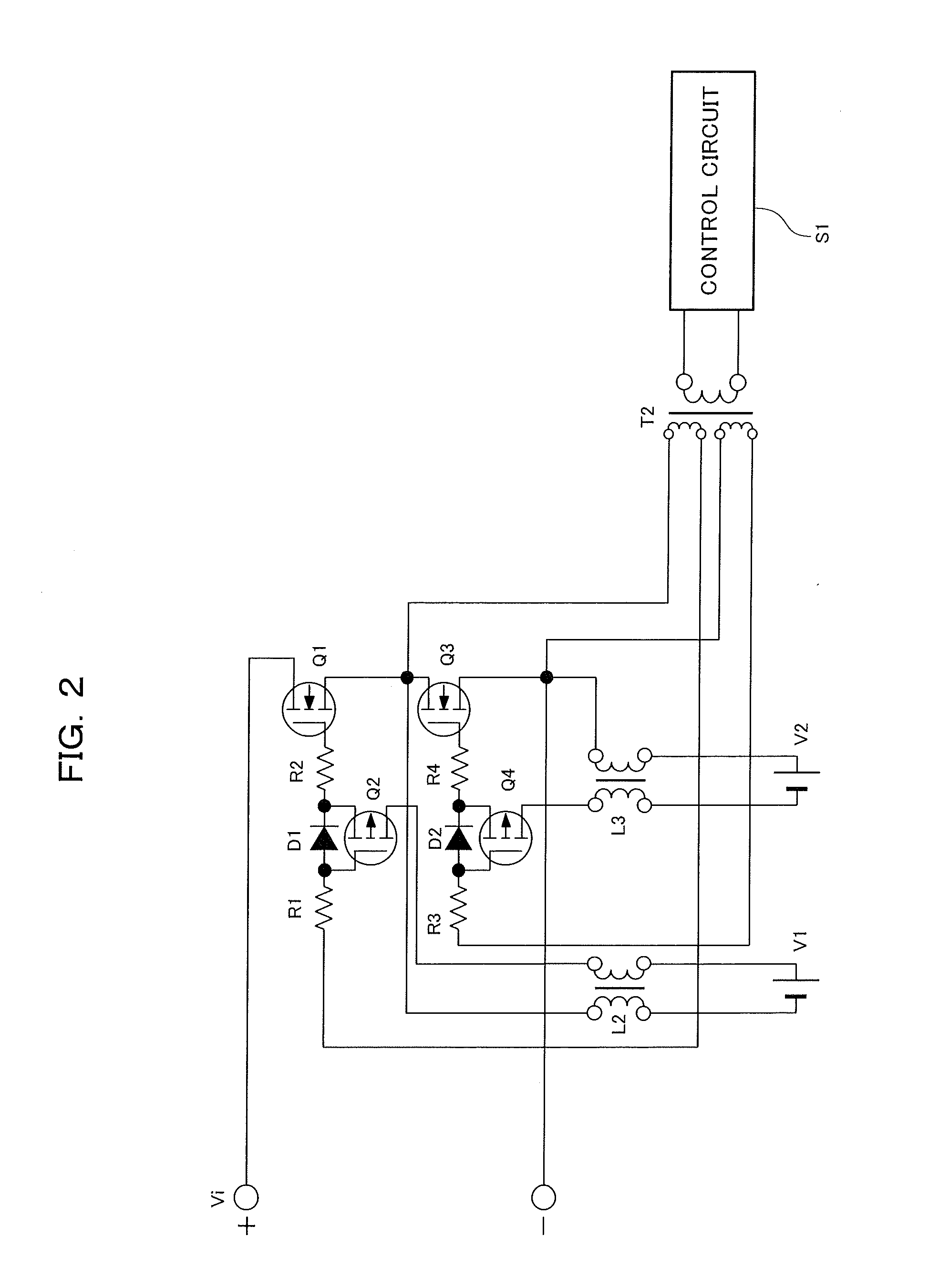
[0057]The following will describe a switching power supply according to a second embodiment of the present invention.

[0058]Referring to FIG. 4, the switching power supply of the second embodiment will be described below in which a reverse bias circuit is simplified in contrast to the circuit configuration of the first embodiment.

[0059]FIG. 4 is a circuit diagram showing the structural example of the switching power supply according to the second embodiment.

[0060]As shown in FIG. 4, the reverse bias circuit in the switching power supply of the second embodiment is configured such that a choke coil L2 is connected to a drawing transistor Q2 in each power supply circuit Z1′, a reverse bias voltage is supplied from a bias power supply V1 through each of the choke coils L2, a choke coil L3 is connected to a drawing transistor Q4 in each of the power supply circuits Z1′, and a reverse bias voltage is supplied from a bias power supply V2 through the single choke coil L3.

[0061]According to ...


PUM


Abstract

A plurality of power supply circuits Z1′ are provided according to a load capacity. The power supply circuits Z1′ have sides connected in parallel on the side of a direct current input Vi and have sides connected in series on the sides of alternating current outputs Ao. A rectifying circuit DC1 is connected via a resonance circuit Z2 across a combined output of the serially connected sides of the power supply circuits Z1′ on the sides of the alternating current outputs Ao. Switching frequencies are simultaneously controlled by a single control signal outputted from a control circuit S1 based on a direct current output voltage detected from the rectifying circuit DC1 through a detection resistor R5.

Description

TECHNICAL FIELD[0001]The present invention relates to a resonant switching power supply which obtains a stable direct current output by switching a direct current input and has a resonance circuit in a switching control section.BACKGROUND ART[0002]In the prior art, switching power supplies characterized by small sizes, light weights, and high power efficiencies have been widely used as power supplies of electronic equipment and so on. As this kind of switching power supply, the following will describe a resonant switching power supply which obtains a direct current output by switching a direct current input into a constant voltage and has a serial-parallel resonance circuit in a switching control section to satisfactorily obtain a constant voltage over a wide range of changes of a load capacity.[0003]As a switching power supply capable of changing a direct current output voltage Vo over a wide range, supplying a stable direct current output voltage to a load, and minimizing a power ...

Claims


Application Information

Patent Timeline
Patent Type & Authority Patents(United States)
IPC IPC(8): H02M3/335
CPCH02M1/08H02M3/33507H02M3/33569H02M3/337H02M2001/0077Y02B70/1433Y02B70/10H02M1/0077H02M3/33571H02M3/01
Inventor NISHIHARA, HIDEKIKOMATSU, AKEYUKI
Owner PANASONIC HEALTHCARE HLDG CO LTD
Why Eureka
Try Eureka