Digital silicon photomultiplier for TOF PET

a digital silicon and photomultiplier technology, applied in the field of radioation detection arts, can solve the problems of not being able to meet the requirements of small pixel sizes, not being able to meet the requirements of high resolution, and being bulky in the pixel size, so as to improve the manufacturing yield of the detector device, improve the spatial detector resolution, and high data-rate radiation detection

Active Publication Date: 2013-03-12
KONINKLIJKE PHILIPS ELECTRONICS NV
View PDF29 Cites 72 Cited by
  • Summary
  • Abstract
  • Description
  • Claims
  • Application Information

AI Technical Summary

Benefits of technology

[0015]One advantage resides in providing high data-rate radiation detection for TOF-PET, single photon emission computed tomography (SPECT), transmission computed tomography (CT), astronomy, and other applications.
[0016]Another advantage resides in providing a digital radiation detector output.
[0017]Another

Problems solved by technology

PMTs are generally fast enough to perform TOF-PET imaging; however, PMTs are bulky, require high voltage biasing, and are not well-suited for small pixel sizes desirable for high resolution.
Conventional photodiodes are fast enough for TOF-PET, but lack internal amplification, leading to poor signal-to-noise ratios.
Avalanche photodiodes can also be used; however, avalanche photodiodes typicall

Method used


Image

  • Digital silicon photomultiplier for TOF PET
  • Digital silicon photomultiplier for TOF PET
  • Digital silicon photomultiplier for TOF PET

Examples


Embodiment Construction

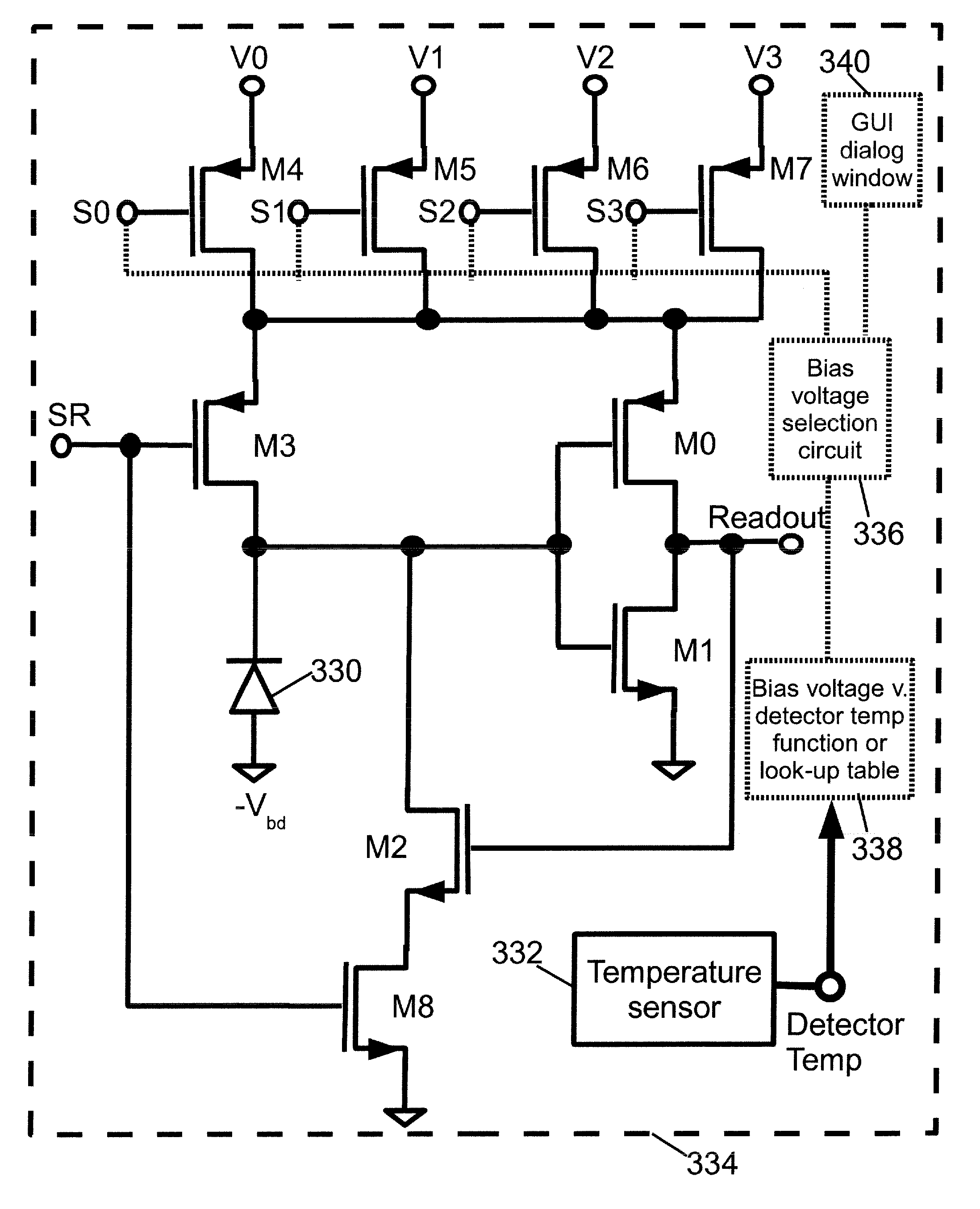
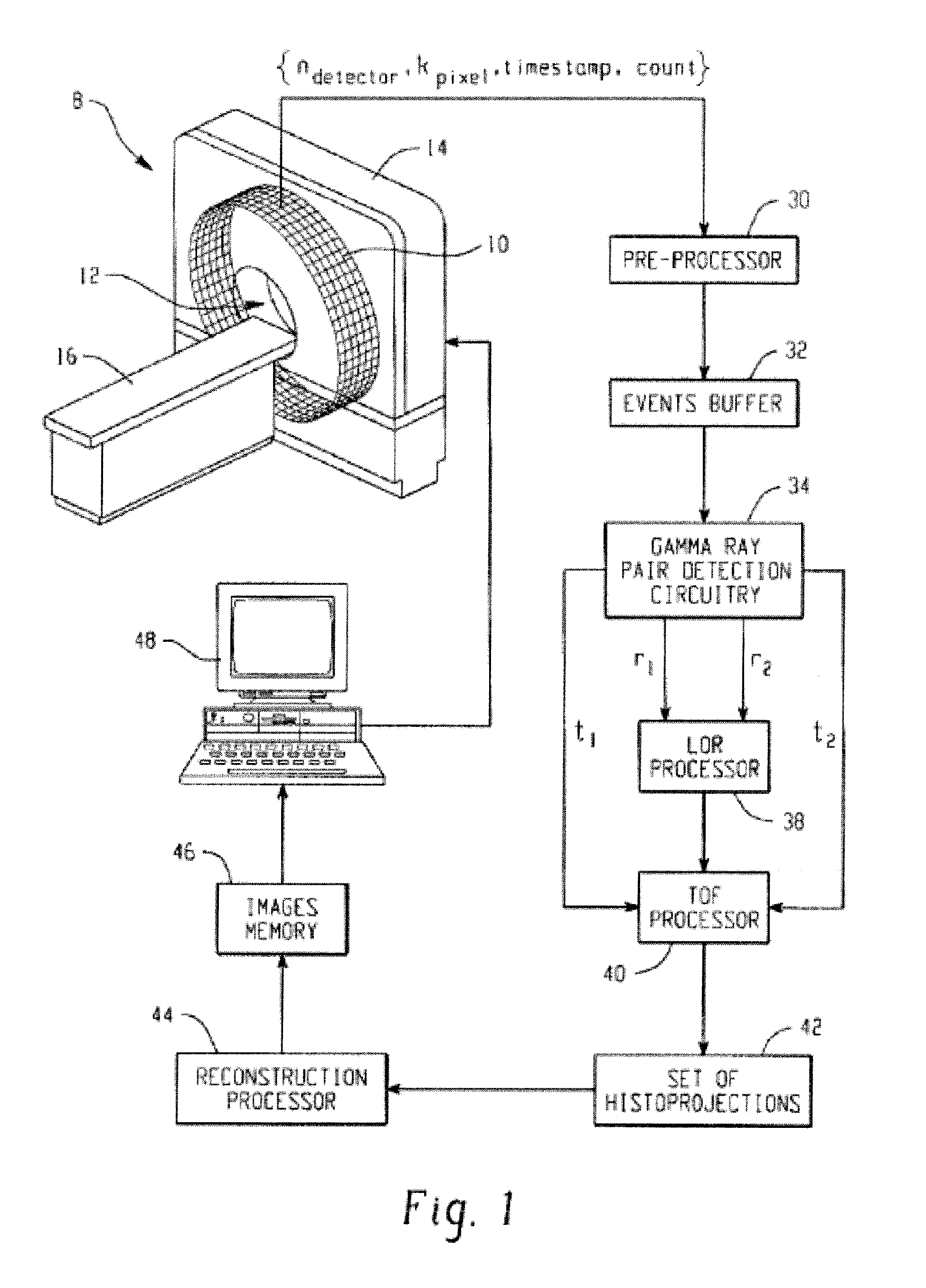
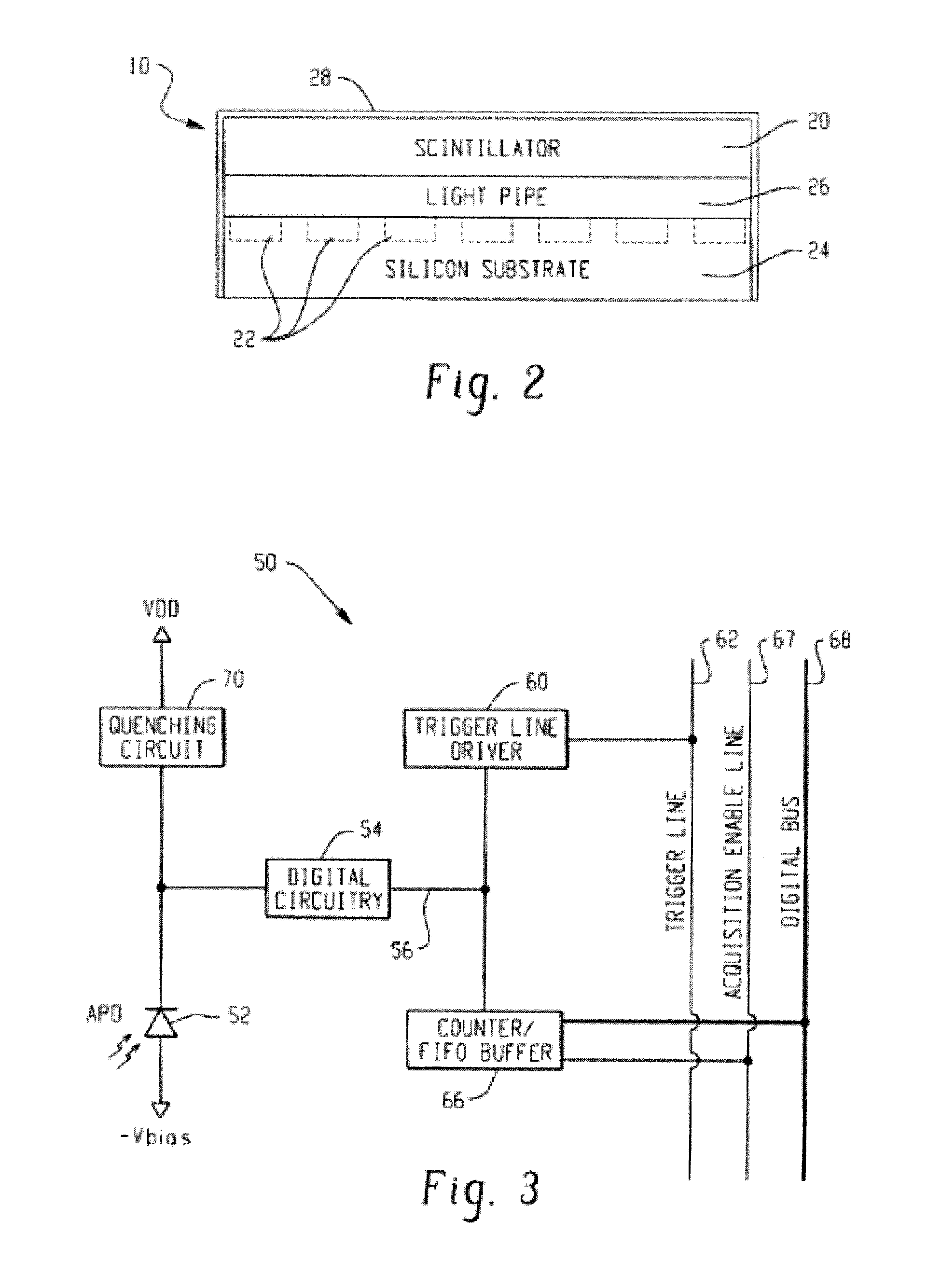
[0039]With reference to FIG. 1, a time-of-flight positron emission tomography (TOF-PET) scanner 8 includes a plurality of radiation detectors 10 arranged to view an imaging region 12. In FIG. 1, the plurality of radiation detectors 10 are arranged in several rings of detectors along an axial direction; however, other arrangements of radiation detectors can be used. Moreover, it is to be appreciated that the plurality of radiation detectors 10 is diagrammatically illustrated; typically the radiation detectors are housed within a housing 14 of the scanner 8 and thus are not visible from the outside, and typically each ring of radiation detectors includes hundreds or thousands of radiation detectors. In some PET scanners, only a single ring of radiation detectors is provided, in others, two, three, four, five, or more rings of radiation detectors are provided. It should be appreciated that detector heads can be used in place of the detector ring structure shown in the Figures. The TOF-...


PUM


Abstract

A radiation detector includes an array of detector pixels each including an array of detector cells. Each detector cell includes a photodiode biased in a breakdown region and digital circuitry coupled with the photodiode and configured to output a first digital value in a quiescent state and a second digital value responsive to photon detection by the photodiode. Digital triggering circuitry is configured to output a trigger signal indicative of a start of an integration time period responsive to a selected number of one or more of the detector cells transitioning from the first digital value to the second digital value. Readout digital circuitry accumulates a count of a number of transitions of detector cells of the array of detector cells from the first digital state to the second digital state over the integration time period.

Description

CROSS REFERENCE TO RELATED APPLICATIONS[0001]This application is a continuation-in-part of U.S. Ser. No. 11 / 467,670 filed Aug. 28, 2006 which is a continuation of PCT application number PCT / IB2006 / 051089 filed Apr. 10, 2006 which claims the benefit of U.S. provisional application Ser. No. 60 / 674,034 filed Apr. 22, 2005 and U.S. provisional application Ser. No. 60 / 682,246 filed May 18, 2005. U.S. Ser. No. 11 / 467,670 filed Aug. 28, 2006 is incorporated herein by reference in its entirety. U.S. published application 2008 / 0203309 A1 published Aug. 28, 2008 (corresponding to U.S. Ser. No. 11 / 467,670) is incorporated herein by reference in its entirety. PCT application no. PCT / IB2006 / 051089 is incorporated herein by reference in its entirety. PCT publication WO 2006 / 111883 A2 published Oct. 26, 2006 (corresponding to PCT / IB2006 / 051089) is incorporated herein by reference in its entirety. U.S. provisional application Ser. No. 60 / 674,034 filed Apr. 22, 2005 is incorporated herein by referen...

Claims


Application Information

Patent Timeline
IPC IPC(8): G01T1/208
CPCG01T1/2018G01T1/208G01T1/2985G01T1/1642A61B6/037G01T1/20184
Inventor FRACH, THOMASPRESCHER, GORDIAN
Owner KONINKLIJKE PHILIPS ELECTRONICS NV
Why Eureka
Try Eureka