
Memory controller supporting redundant synchronous memories

a memory controller and synchronous memory technology, applied in the direction of redundant hardware error correction, input/output to record carriers, instruments, etc., can solve the problems of degrading the overall performance of the server, limiting the performance of the server system, and increasing the number of i/o interrupts received by the server

Inactive Publication Date: 2005-12-20
HEWLETT-PACKARD ENTERPRISE DEV LP
View PDF21 Cites 24 Cited by
  • Summary
  • Abstract
  • Description
  • Claims
  • Application Information

AI Technical Summary

Benefits of technology

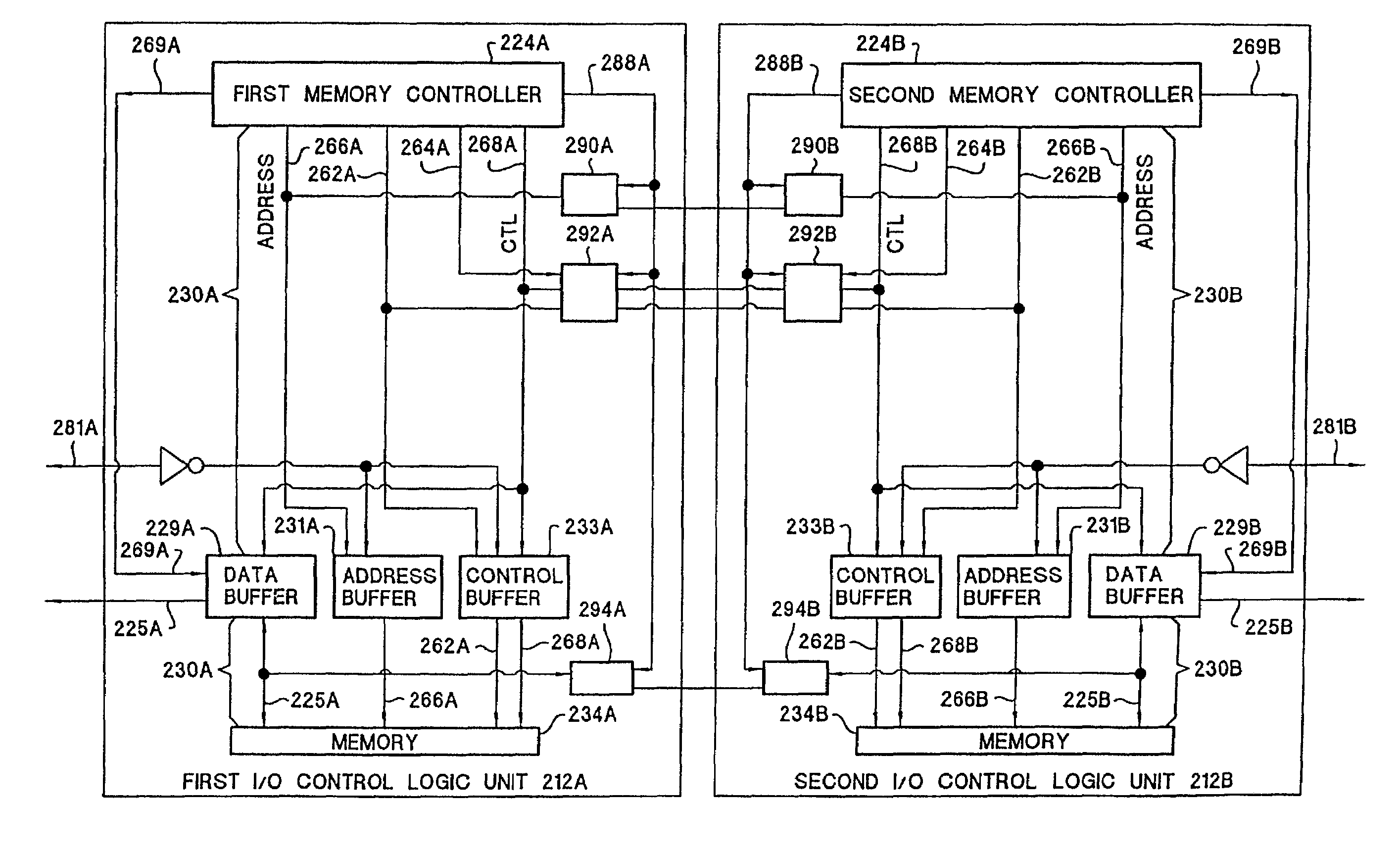
[0009]Preferably, there are two I / O control logic units that each contain the same components and are intended to replace each other in the event one of the I / O control logic units malfunctions. A master I / O control logic unit act as the master unit receiving I / O transactions from the host server and the external peripheral devices. The slave I / O control logic unit acts a slave unit that is in a quiescent state performing small tasks until the master device becomes non-operational. The memories in each I / O control logic unit are synchronized so that in the event the master I / O control logic unit malfunctions, the slave I / O control logic unit can resume processing the I / O transactions.

Problems solved by technology

The performance of server systems has been limited by the low bandwidth associated with I / O subsystems.
However this causes an increase in the number of I / O interrupts received by the server.
The increased number of I / O interrupts unnecessarily consumes the server's time thereby degrading the overall performance of the server.
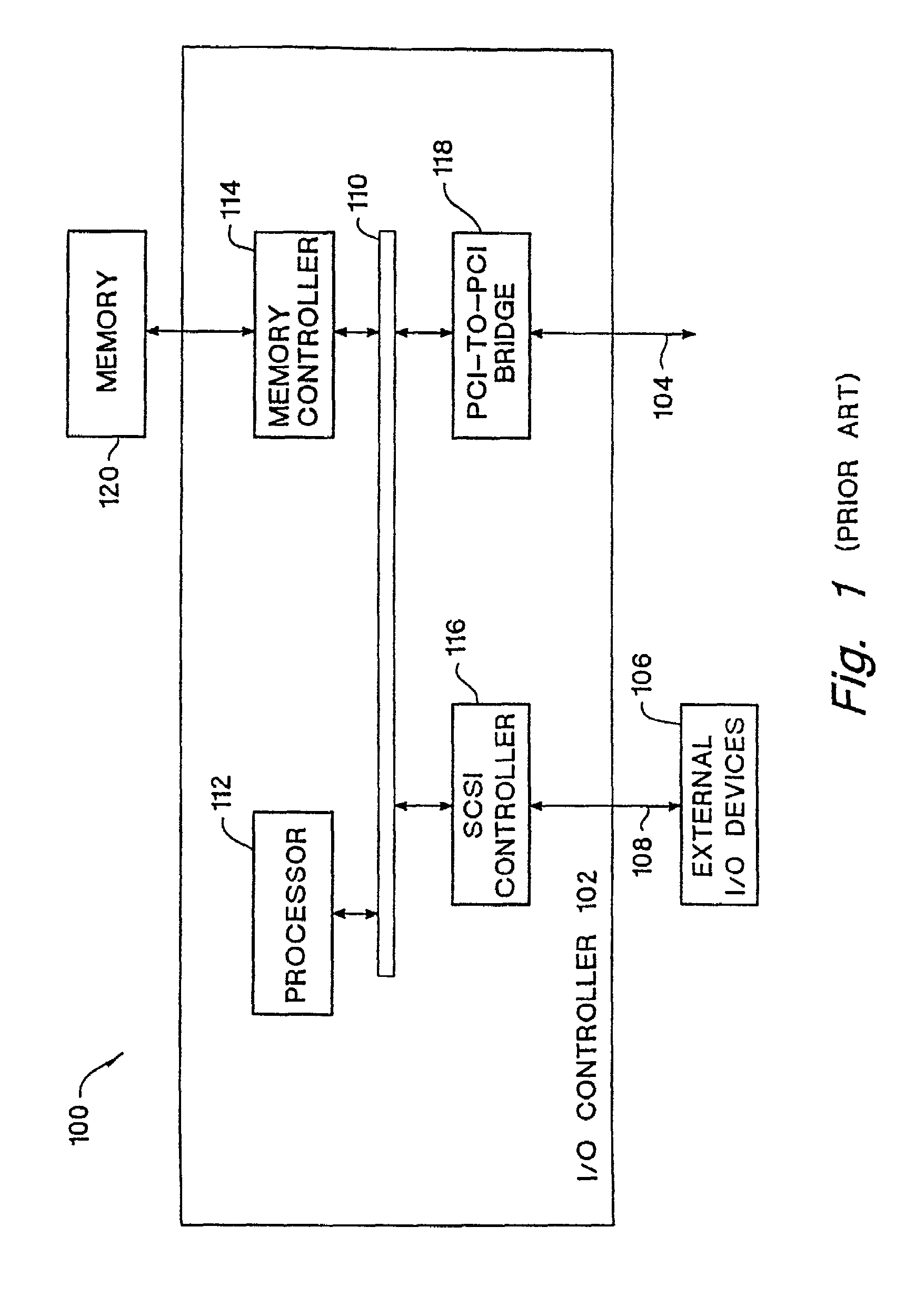
A drawback with the design of this particular I / O controller 102 is that it is not fault tolerant.
Such a memory failure is apparent when an intolerable number of parity errors is detected.

Method used


Image

  • Memory controller supporting redundant synchronous memories
  • Memory controller supporting redundant synchronous memories
  • Memory controller supporting redundant synchronous memories

Examples


Embodiment Construction

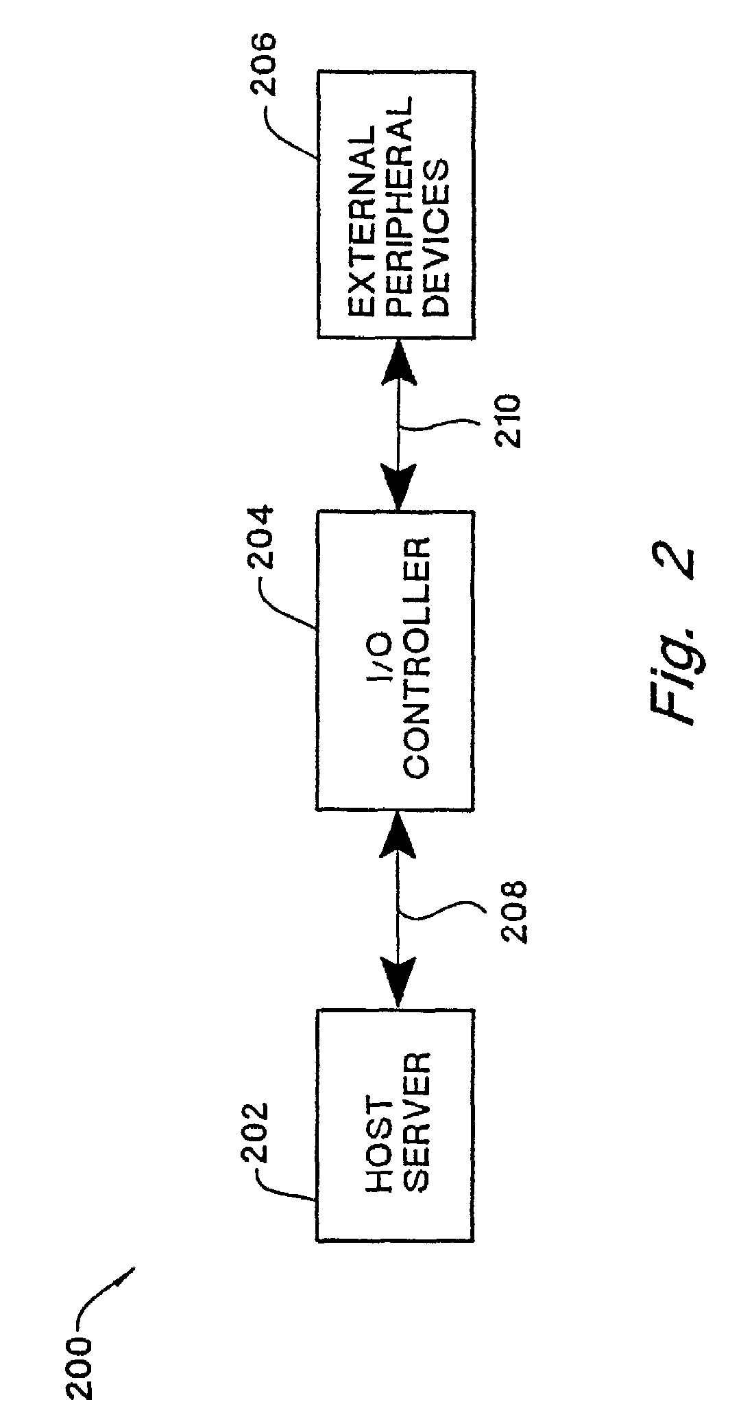
[0025]FIG. 2 illustrates a computer system 200 employing the technology of the present invention. There is shown a computer system 200 including a host server 202, an I / O controller 204, and external peripheral devices 206. The host server 202 can be any type of computer or data processor such as but not limited to personal computers, workstations, server machines, mainframes, and the like. Preferably, the host server 202 is a server computer from the Hewlett Packard NetServer product line. The I / O controller 204 is any type of processing device that has the ability to control the exchange of data between an external processor and peripheral devices. In a preferred embodiment, the 110 controller 204 is an Intelligent I / O (120) controller supporting the 120 specification. The external peripheral devices 206 can be any type of data unit such as but not limited to storage devices, disk drives, tape drives, CD ROM devices, and the like.

[0026]The host server 202 is coupled to the I / O con...


PUM


Abstract

A reliable fault-tolerant I / O controller supporting redundant synchronous memories is described. The I / O controller includes multiple I / O control logic units where each I / O control logic unit is in communication with a host server and external peripheral devices. Each I / O control logic unit includes a processor, a memory, and a memory controller. A master I / O control logic unit services I / O transactions from the host server and the external peripheral devices. A slave I / O control logic unit operates in a quiescent state until the master I / O control logic unit experiences a memory failure. At such time, the slave I / O control logic unit resumes operation of the I / O controller. In order to facilitate the switchover from the master I / O control logic unit to the slave I / O control logic unit, the master memory controller performs concurrent memory write operations in both the master and slave memories. The concurrent memory write operations ensure that the memories in both I / O control logic units are in a consistent state in order for the switchover to occur without loss of data.

Description

CROSS REFERENCE TO RELATED APPLICATION(S)[0001]This is a divisional of application Ser. No. 09 / 085,204 filed on May 27, 1998, now U.S. Pat. No. 6,243,829.FIELD OF THE INVENTION[0002]The present invention relates generally to computer systems using input / output (I / O) controllers. More particularly, the invention relates to a fault tolerant I / O controller having redundant synchronous memories.BACKGROUND OF THE INVENTION[0003]The performance of server systems has been limited by the low bandwidth associated with I / O subsystems. Attempts to improve this performance bottleneck have been geared towards increasing the I / O bandwidth. However this causes an increase in the number of I / O interrupts received by the server. The increased number of I / O interrupts unnecessarily consumes the server's time thereby degrading the overall performance of the server.[0004]To overcome this bottleneck, a separate I / O processor or controller is typically used to perform the tasks that would normally be per...

Claims


Application Information

Patent Timeline
Patent Type & Authority Patents(United States)
IPC IPC(8): G06F3/06G06F12/16G06F11/00G06F11/16G06F11/20G06F13/00
CPCG06F11/2005G06F11/2097
Inventor CHAN, JONG
Owner HEWLETT-PACKARD ENTERPRISE DEV LP
Learn More