
Articulating clip applier cartridge

a technology of applier cartridge and clip, which is applied in the field of surgical clip appliers, can solve the problems of reduced field of view and complicated application of clip

Active Publication Date: 2013-03-26
TYCO HEALTHCARE GRP LP
View PDF617 Cites 1115 Cited by
  • Summary
  • Abstract
  • Description
  • Claims
  • Application Information

AI Technical Summary

Benefits of technology

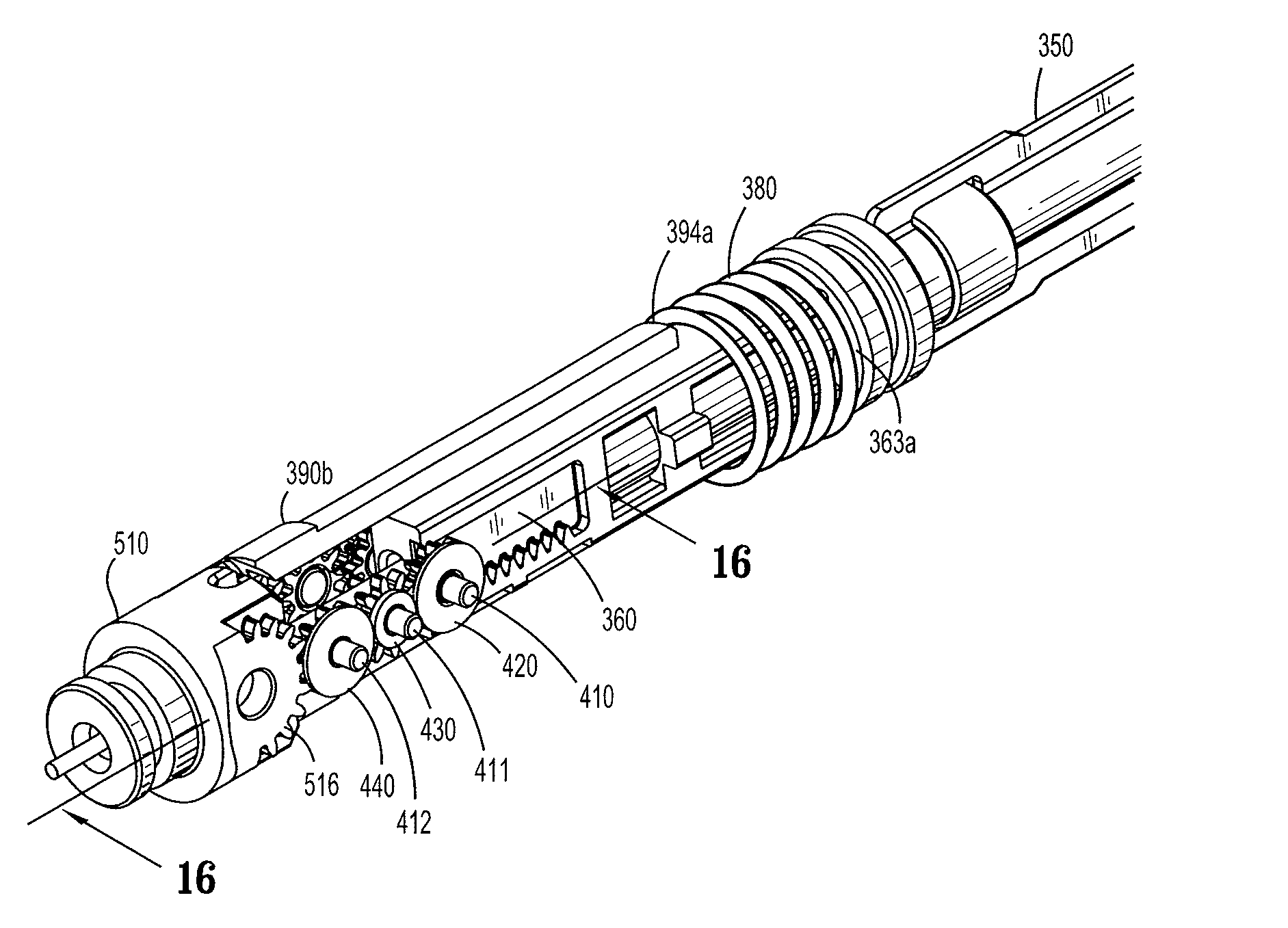
The present patent is about a surgical clip applier that includes a housing, a drive assembly, a shaft assembly, and a trigger. The shaft assembly includes a first tubular member and a second tubular member that are pivotally connected through a common pivot axis. The second tubular member has a jaw assembly and a clip cartridge containing a plurality of clips. The surgical clip applier also includes an articulation mechanism that allows the second tubular member to pivot about the pivot axis at an angle of up to 90° from the first tubular member. The articulation mechanism includes a control knob that is rotatable to retract a rack and extend the rack distally. The second tubular member has a longitudinal axis and a distal end. The flexible drive cable transfers both a translational force and a rotational force from the inside of the housing into the second tubular member. The surgical clip applier provides a pivotal force to pivot the second tubular member about the pivot axis at an angle of up to 90° from the first tubular member. The articulation mechanism includes a rack and a band that are connected to the drive assembly. The band has a contoured outer surface that receives and transmits the rotational force from the inner surface of the dial. The second tubular member includes a jaw assembly and a clip cartridge containing a plurality of clips. The surgical clip applier provides a flexible and efficient tool for applying surgical clips to body tissue.

Problems solved by technology

Consequently, application of clips may be complicated by a reduced field of view or reduced tactile feedback for the user at the proximal end of the device.

Method used


Image

  • Articulating clip applier cartridge
  • Articulating clip applier cartridge
  • Articulating clip applier cartridge

Examples


Embodiment Construction

[0112]Embodiments of surgical clip appliers in accordance with the present disclosure will now be described in detail with reference to the drawing figures wherein like reference numerals identify similar or identical structural elements. As shown in the drawings and described throughout the following description, as is traditional when referring to relative positioning on a surgical instrument, the term “proximal” refers to the end of the apparatus which is closer to the user and the term “distal” refers to the end of the apparatus which is further away from the user.

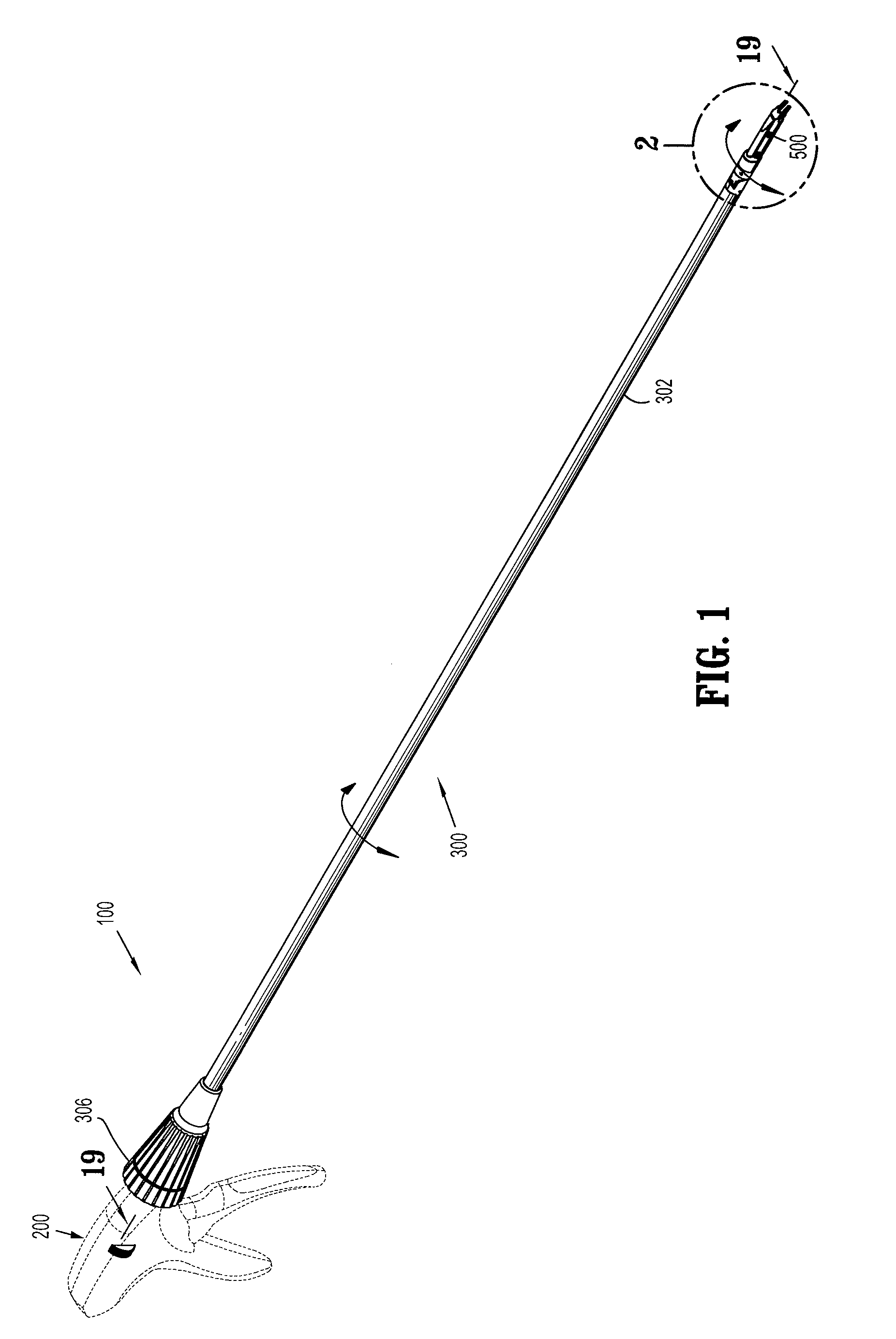
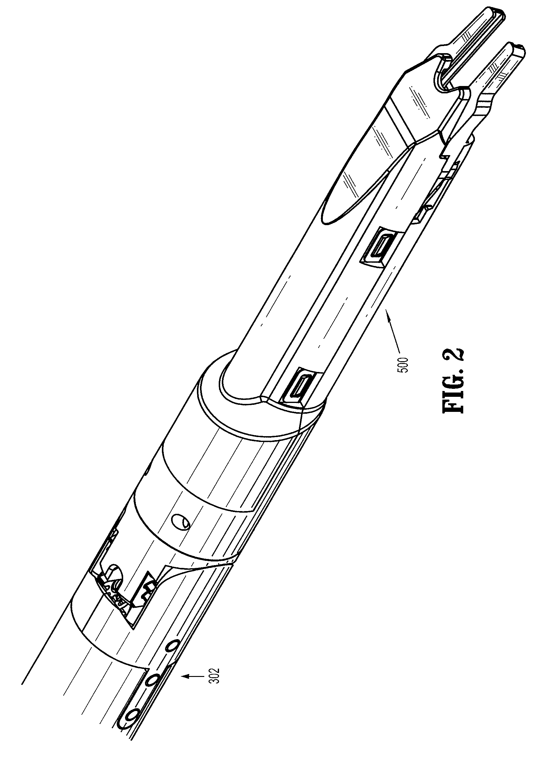
[0113]With reference to FIG. 1, reference numeral 100 designates an embodiment of the presently disclosed surgical clip applier. In the interest of brevity, the present disclosure focuses on an articulation mechanism and a clip applying end mechanism of surgical clip applier 100. U.S. Pat. No. 7,637,917, filed on Oct. 7, 2005, describes in detail the structure and operation of a surgical clip applier that may incorpora...


PUM


Abstract

An end effector is provided and includes a distal housing portion and a proximal housing portion interconnected to one another by a knuckle portion, wherein the knuckle portion permits rotation of the distal housing portion relative thereto and articulation of the distal housing portion relative to the proximal housing portion; a jaw assembly supported in the distal end of the distal housing portion, the jaw assembly including a first jaw and a second jaw movable between a spaced apart and an approximated position; and a plurality of fasteners loaded within the distal housing portion, each of the plurality of fasteners defining a fastener axis extending in a direction substantially parallel to a pair of legs thereof, each of the plurality of fasteners being arranged within the base portion such that the fastener axis is disposed at an angle with respect to a longitudinal axis of the distal housing portion.

Description

CROSS REFERENCE TO RELATED APPLICATION[0001]The present application claims the benefit of and priority to U.S. Provisional Application Ser. No. 61 / 368,463 filed on Jul. 28, 2010, the entire contents of which are incorporated herein by reference.BACKGROUND[0002]1. Technical Field[0003]The present disclosure relates to surgical clip appliers and, more particularly, to a novel articulating endoscopic surgical fastener applier cartridge.[0004]2. Background of Related Art[0005]Endoscopic staplers and clip appliers are known in the art and are used for a number of distinct and useful surgical procedures. In the case of a laparoscopic surgical procedure, access to the interior of an abdomen is achieved through narrow tubes or cannulas inserted through a small entrance incision in the skin. Minimally invasive procedures performed elsewhere in the body are often generally referred to as endoscopic procedures. Typically, a tube or cannula device is extended into the patient's body through the...

Claims


Application Information

Patent Timeline
Patent Type & Authority Patents(United States)
IPC IPC(8): A61B17/10
CPCA61B17/1285A61B17/10A61B2017/2943A61B2017/2927A61B17/068A61B17/07207A61B17/12A61B2017/07228A61B2017/2929
Inventor WHITFIELD, KENNETHRETHY, CSABA L.
Owner TYCO HEALTHCARE GRP LP
Learn More