System and method for correcting spinal deformity

a spinal deformity and system technology, applied in the field of system and method for correcting spinal deformity, can solve the problems of system bulkiness and inability to specifically capitalize on the properties of flexible linkage members

Active Publication Date: 2013-03-26
WARSAW ORTHOPEDIC INC
View PDF9 Cites 76 Cited by
  • Summary
  • Abstract
  • Description
  • Claims
  • Application Information

AI Technical Summary

Problems solved by technology

These systems remain bulky and do not specifically capitalize on the properties of the flexible linkage members.

Method used


Image

  • System and method for correcting spinal deformity
  • System and method for correcting spinal deformity
  • System and method for correcting spinal deformity

Examples


Embodiment Construction

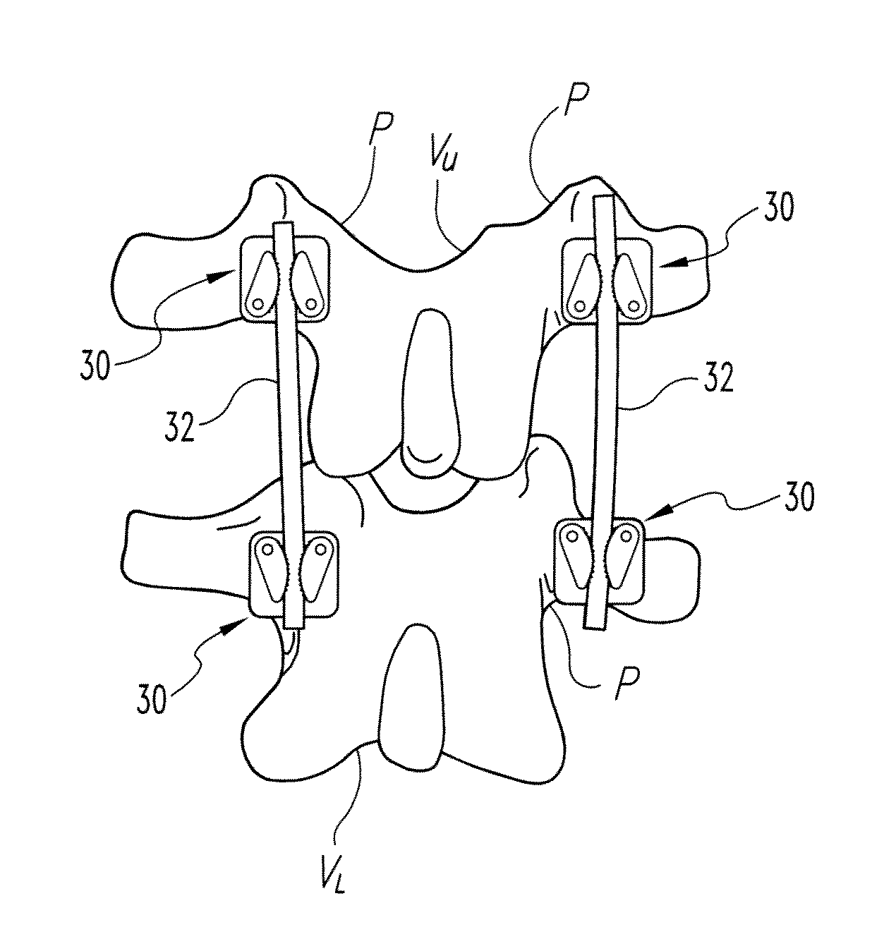
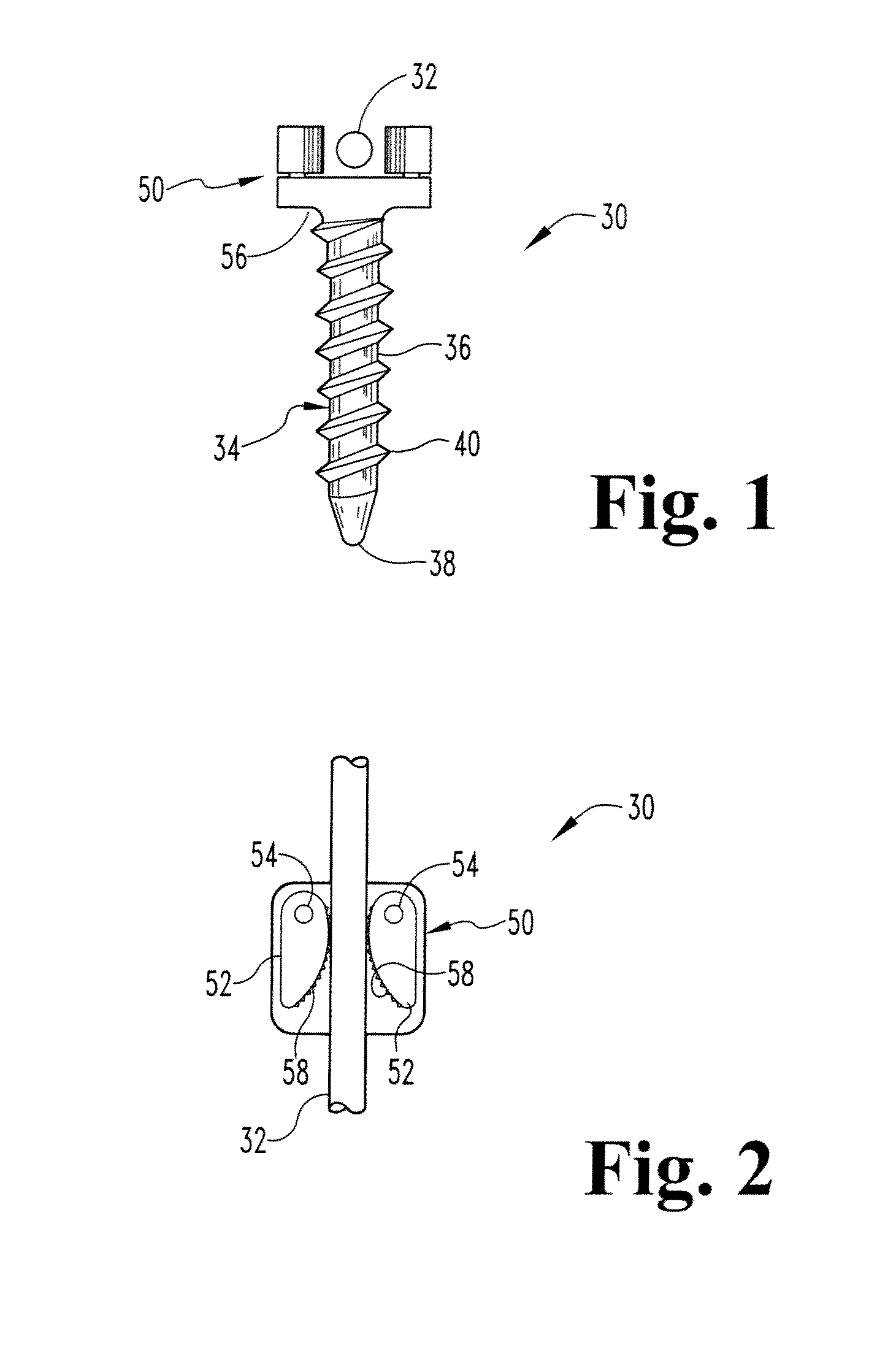
[0030]Referring now to the drawings and in particular FIG. 1, an anchor of one embodiment of the present invention is designated in its entirety by the reference number 30. The anchor 30 is intended to attach an elongate flexible member 32 to bone (e.g., a pedicle of a vertebra) as will be described in further detail below. As further shown in FIG. 1, the anchor 30 includes a base, generally designated by 34 for attaching the anchor to bone. The base 34 includes a longitudinal shaft 36 having a tip 38 at one end. In one embodiment, the tip 38 has a rounded point for entering bone without inadvertently damaging surrounding bone or tissue. A thread 40 extends along the shaft 36 thereby forming a screw for advancing the shaft into the bone and holding the shaft in place in the bone. A connector, generally designated by 50 is mounted on the base 34.

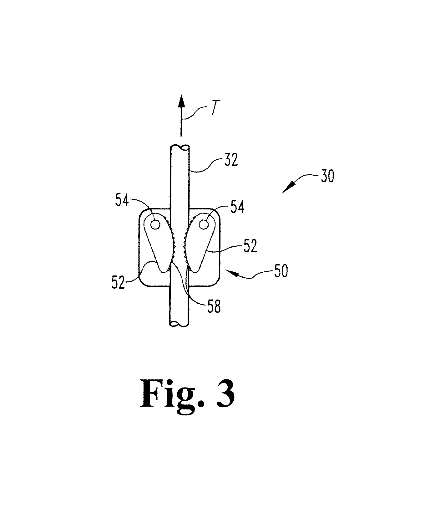
[0031]As illustrated in FIG. 2, the connector 50 includes one pair of cams 52 pivotally mounted on pins 54 attached to a head 56 (FIG. 1) of...


PUM


Abstract

An anchor for attaching an elongate flexible member to bone. The anchor includes a base adapted for attaching to bone and a connector mounted on the base. The connector includes a cam positioned for engaging the flexible member when the base is attached to bone. The cam is pivotable between an open position in which the flexible member may be moved relative to the connector and a closed position in which the cam engages the flexible member so the flexible member is fixed relative to the connector.

Description

CROSS-REFERENCE TO RELATED APPLICATIONS[0001]This application claims priority from U.S. Provisional Patent Application No. 60 / 839,028 filed Aug. 21, 2006, entitled, “TECHNIQUES AND ENSEMBLE OF DEVICES FOR SPINAL SURGERY WITH FLEXIBLE LINKAGE ELEMENTS, ATTACHMENT SYSTEMS AND ANCHORAGE MEMBERS,” which is hereby incorporated by reference.BACKGROUND[0002]This invention generally relates to a system and methods for correcting or treating spinal deformities and other conditions through a non-fusion procedure.[0003]A variety of systems and devices are available to correct or stabilize a spinal column. Some of these systems include anchors adapted to attach to vertebrae and linking elements such as rods and plates that rigidly attach to the anchors to rigidly fasten several vertebrae together to promote the vertebrae to fuse together. Bone material may be added to further promote fusion of the vertebrae. Other systems have been devised that do not promote fusion. If fusion is not desired, b...

Claims


Application Information

Patent Timeline
Patent Type & Authority Patents(United States)
IPC IPC(8): A61B17/70
CPCA61B17/7001A61B17/7022A61B17/8605A61B17/8685
Inventor SCHWAB, FRANK J.
Owner WARSAW ORTHOPEDIC INC
Why Eureka
Try Eureka