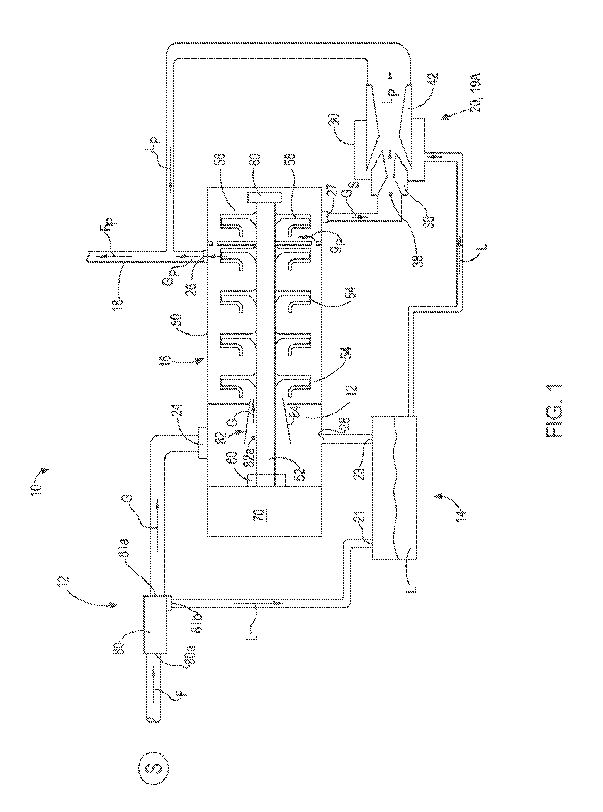
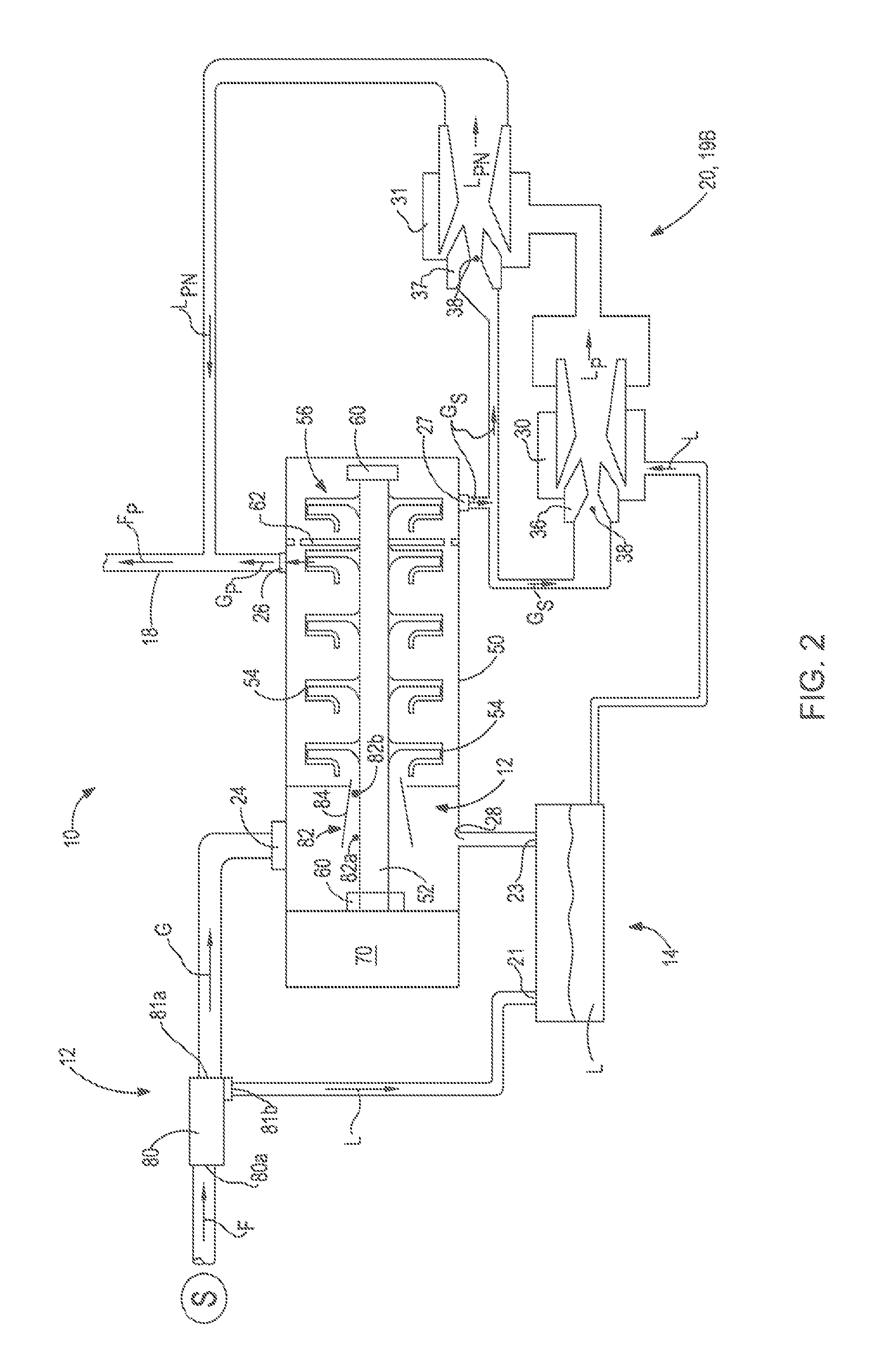
Compressor assembly including separator and ejector pump

a technology of separator and ejector, which is applied in the direction of positive displacement liquid engine, piston pump, separation process, etc., can solve the problem of reducing the overall efficiency of the compressor

Inactive Publication Date: 2013-04-02
DRESSER RAND CO
View PDF399 Cites 11 Cited by
  • Summary
  • Abstract
  • Description
  • Claims
  • Application Information

AI Technical Summary

Problems solved by technology

Pumping the liquid with a centrifugal pump requires additional power input, thus reducing the overall efficiency of the compressor.

Method used


Image

  • Compressor assembly including separator and ejector pump
  • Compressor assembly including separator and ejector pump
  • Compressor assembly including separator and ejector pump

Examples


Embodiment Construction

[0014]It is to be understood that the following disclosure describes several exemplary embodiments for implementing different features, structures, or functions of the invention. Exemplary embodiments of components, arrangements, and configurations are described below to simplify the present disclosure, however, these exemplary embodiments are provided merely as examples and are not intended to limit the scope of the invention. Additionally, the present disclosure may repeat reference numerals and / or letters in the various exemplary embodiments and across the Figures provided herein. This repetition is for the purpose of simplicity and clarity and does not in itself dictate a relationship between the various exemplary embodiments and / or configurations discussed in the various Figures. Moreover, the formation of a first feature over or on a second feature in the description that follows may include embodiments in which the first and second features are formed in direct contact, and m...


PUM

PropertyMeasurementUnit
pressureaaaaaaaaaa
pressureaaaaaaaaaa
pressureaaaaaaaaaa

Abstract

A fluid processing device for processing a multiphase fluid stream including a mixture of at least a gas and a liquid is disclosed. The fluid processing device may include at least one separator configured to separate the fluid stream into a liquid portion and a gaseous portion and deposit the liquid portion into a liquid reservoir. The gaseous portion may be directed to a compressor configured to pressurize and discharge a pressurized gas into a fluid discharge line. A portion of the pressurized gas may be further pressurized and directed to at least one ejector pump fluidly coupled to the liquid reservoir and configured to draw in liquid and discharge pressurized liquid into the fluid discharge line.

Description

[0001]This application is a United States national phase application of co-pending international patent application number PCT / US2009 / 036142, filed Mar. 5, 2009, which claims the benefit of the filing date of U.S. provisional patent application No. 61 / 068,385, filed Mar. 5, 2008, the disclosures of which are incorporated herein by reference.[0002]A variety of devices for handling fluid streams, such as separators, compressors, and pumps, are known. A separator basically functions to separate a fluid stream into different phases, such as into liquid and gaseous portions, and / or may be used to remove solid matter from a fluid stream. Compressors and pumps basically function to compress or pressurize gases and pressurize liquids, respectively, often for the purpose of transporting the fluid (e.g., within a pipeline). Typically, when a fluid stream is composed of both gaseous and liquid portions, the fluid stream must first be separated, and then the gaseous portions are directed into a...

Claims


Application Information

Patent Timeline
Patent Type & Authority Patents(United States)
IPC IPC(8): F04B23/08F04F5/24
CPCF04D17/122F04D31/00F04F5/10F04F5/12Y10T137/0318Y10T137/86075Y10T137/86155Y10T137/86163
Inventor KIDD, H. ALLANMAIER, WILLIAM C.CHOCHUA, GOCHA
Owner DRESSER RAND CO
Why Eureka
Try Eureka