

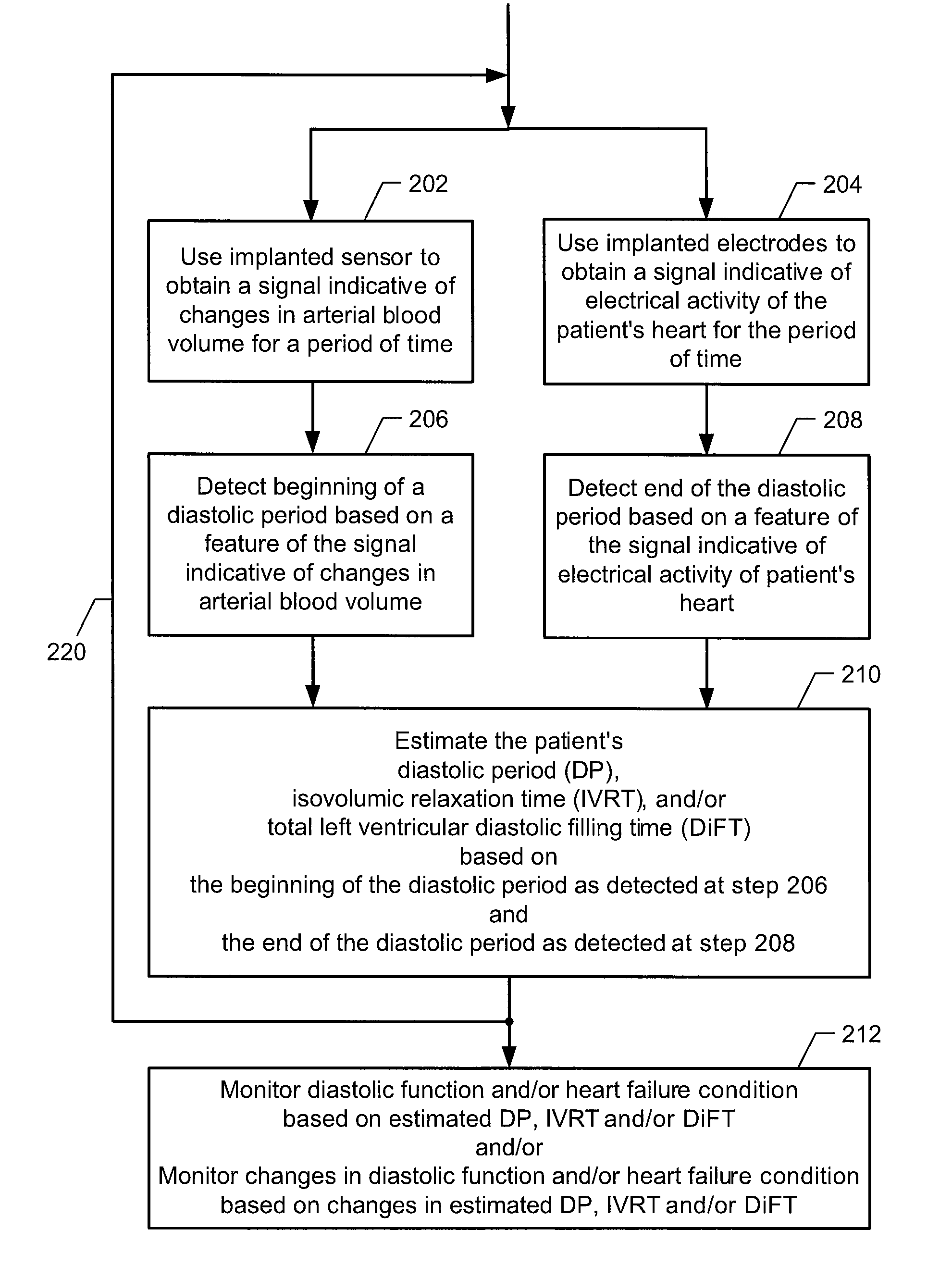
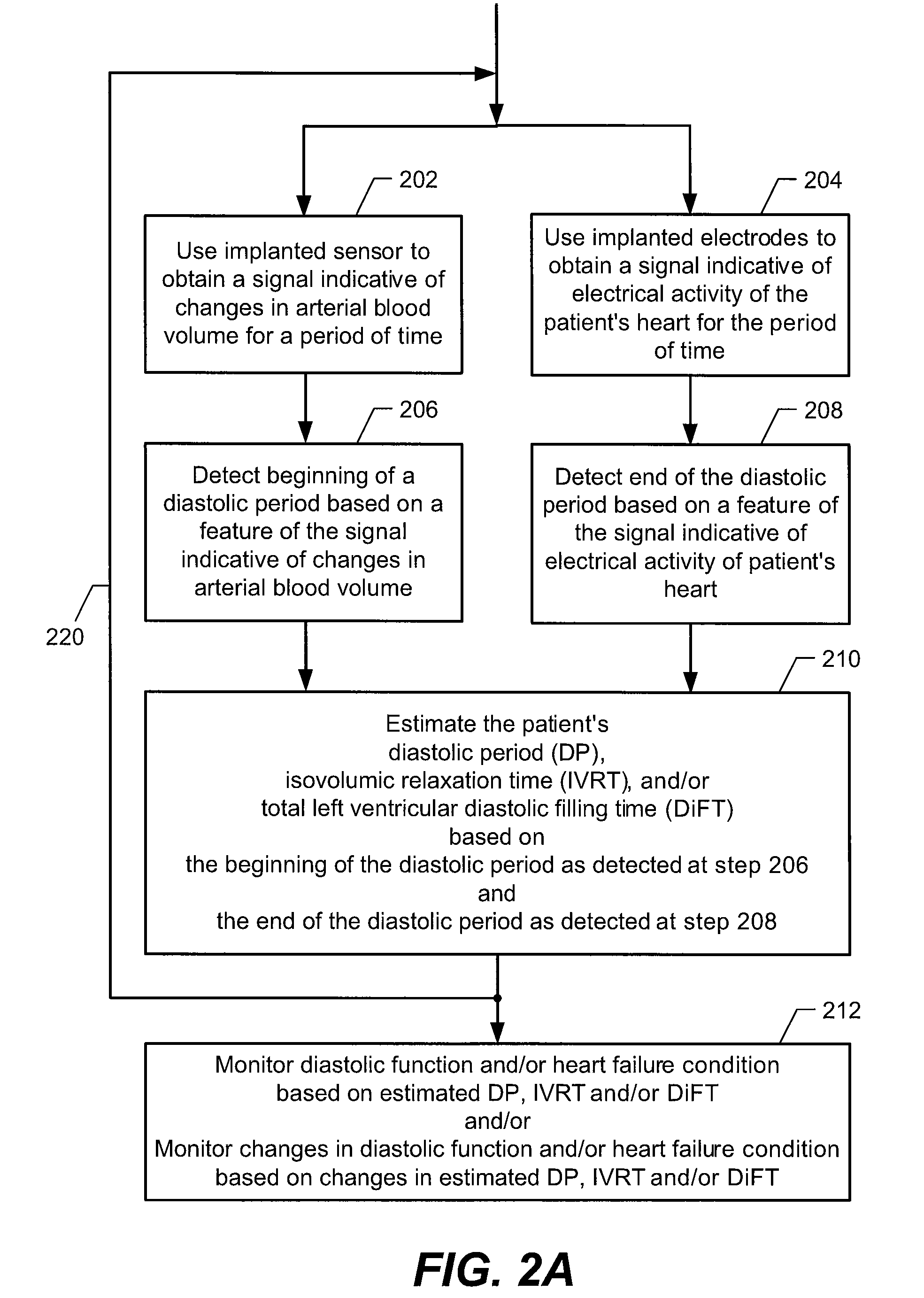
Systems and methods for monitoring DP, IVRT, DiFT, diastolic function and/or HF
a technology of diastolic function and monitoring system, applied in the field of implementation systems, can solve the problems of pulmonary edema, difficult breathing, fluid leakage (i.e. transudate) from the lung's blood vessels into the lung,
- Summary
- Abstract
- Description
- Claims
- Application Information
AI Technical Summary
Problems solved by technology
Method used
Image

Examples
Embodiment Construction
[0030]The following description is of the best modes presently contemplated for practicing various embodiments of the present invention. The description is not to be taken in a limiting sense but is made merely for the purpose of describing the general principles of the invention. The scope of the invention should be ascertained with reference to the claims. In the description of the invention that follows, like numerals or reference designators will be used to refer to like parts or elements throughout. In addition, the first digit of a reference number identifies the drawing in which the reference number first appears.
[0031]It would be apparent to one of skill in the art reading this description that the various embodiments of the present invention, as described below, may be implemented in many different embodiments of hardware, software, firmware, and / or the entities illustrated in the figures. Any actual software, firmware and / or hardware described herein is not limiting of the...
PUM
 Abstract
Description
Claims
Application Information